Optimizing Swarf Management During Machine Tool Reconditioning
Explore technical specifications, conveyor types, and retrofit protocols for integrating advanced swarf management during machine tool reconditioning.
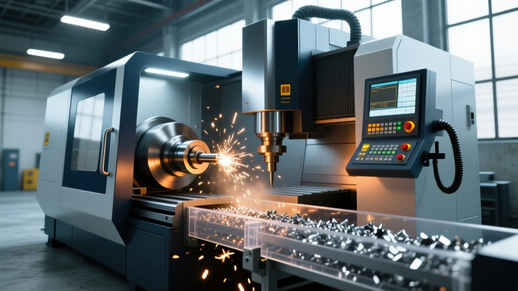
When executing a comprehensive machine tool reconditioning project, the spindle, ball screws, and way covers typically dominate the engineering focus. However, neglecting the chip evacuation and swarf management subsystem guarantees premature way wear, coolant pump cavitation, and catastrophic thermal deformation. Upgrading the chip conveyor during a rebuild is not an aftermarket afterthought; it is a critical integration that dictates the long-term reliability of the reconditioned CNC machining center or lathe.
Proper swarf management directly impacts the chemical stability of the coolant and the physical integrity of the machine casting. According to the Occupational Safety and Health Administration (OSHA), controlling metalworking fluid aerosols and managing chip accumulation is critical for minimizing operator exposure to respiratory hazards and dermatitis. From a mechanical standpoint, trapped swarf acts as an abrasive lapping compound against hydrostatic way bearings and linear guideways, destroying the geometric accuracy achieved during the reconditioning scraping and alignment process.
Conveyor Typology and Application Matrices
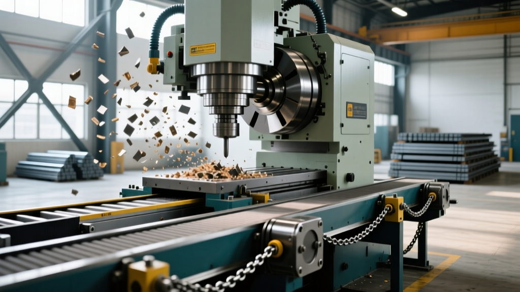
Selecting the correct conveyor architecture requires matching the physical geometry of the generated chips to the mechanical limitations of the conveyor type. A mismatch here is the leading cause of post-reconditioning downtime.
| Conveyor Type | Ideal Chip Morphology | Typical Belt Speed | Reconditioning Integration Complexity |
|---|---|---|---|
| Hinge Belt | Long, stringy, ductile (e.g., 6061-T6 Aluminum, 1018 Steel) | 4 - 8 m/min | Low (Standard drop-in replacement) |
| Scraper / Flight | Fine, powdery, or sludge (e.g., Cast Iron, Brass) | 1.5 - 3 m/min | Medium (Requires trough slope optimization) |
| Auger / Screw | Brittle, fragmented, short (e.g., D2 Tool Steel, Hardened Alloys) | 15 - 30 RPM | High (Requires precise tube clearance machining) |
| Filtermat / Vacuum | Micron-level fines mixed with high-volume coolant | Continuous Index | Very High (Requires coolant tank volumetric redesign) |
Technical Specifications for Drive and Trough Integration
During machine tool reconditioning, the original conveyor drive is often undersized for modern, higher-pressure coolant environments and increased material removal rates. A standard 0.37 kW (1/2 HP) gearmotor is insufficient for heavy-duty horizontal boring mill retrofits.
- Motor Sizing: Specify 1.1 kW to 2.2 kW (1.5 HP to 3 HP) gearmotors with high-torque planetary gearboxes. Brands like SEW-Eurodrive or Nord Gear provide the necessary starting torque to break static friction when the conveyor is packed with dense, compacted chips after a weekend shutdown.
- Trough Material and Gauge: Replace mild steel troughs with 304-grade stainless steel to resist galvanic corrosion from synthetic and semi-synthetic coolants. The steel thickness must be a minimum of 3mm (11 gauge) to prevent vibration-induced fatigue cracking at the weld joints near the head shaft.
- Trough Slope Geometry: The incline section must be engineered to a minimum 35-degree angle for hinge belts to ensure chip shedding, while the horizontal return trough requires a minimum 3-degree slope toward the coolant reservoir to maintain fluid dynamics.
During tank reconditioning, if the coolant return velocity drops below 0.5 m/s in the horizontal trough, fine swarf (particularly cast iron graphite and titanium dust) will settle, compact, and petrify into a concrete-like mass. Always verify the coolant pump GPM rating against the new trough's cross-sectional area to maintain minimum suspension velocity.
Material-Specific Edge Cases in Evacuation
Reconditioning a machine dedicated to specific aerospace or medical alloys requires specialized conveyor modifications that deviate from standard OEM configurations.
Edge Case 1: Machining 6061-T6 Aluminum
High-speed machining of 6061-T6 generates continuous, stringy chips that can exceed 2 meters in length. In a standard hinge belt conveyor, these chips wrap around the head shaft, pull the belt backward, and trip the torque limiter. The Fix: Integrate a hinge belt equipped with a specialized polyurethane wiper blade at the discharge apex and a slip-clutch gearbox. Alternatively, transition to a scraper conveyor with a 12mm pitch chain and AR400 abrasive-resistant steel scrapers.
Edge Case 2: Machining Inconel 718 and Titanium Alloys
These materials generate highly abrasive, work-hardened, and jagged chips that rapidly destroy standard steel hinge plates. The Fix: Specify conveyor belts manufactured from Hardox 450 wear plate with reinforced, oversized hinge pins (minimum 10mm diameter) to resist shear forces during chip jamming events.
Step-by-Step Swarf Management Retrofit Protocol
Integrating a new conveyor system into a reconditioned machine tool requires precise mechanical alignment to prevent binding and premature motor burnout.
- Trough Profiling and Sealing: Machine the machine casting's conveyor mounting flange to ensure absolute flatness. Apply a continuous bead of high-temperature RTV silicone (rated to 200°C) to prevent coolant micro-leaks into the machine base.
- Head Shaft Laser Alignment: Align the conveyor head shaft to the machine base datum using a rotary laser alignment tool. Tolerance must be held to 0.05mm over the length of the shaft to prevent uneven belt tracking.
- Torque Limiter Calibration: Do not rely on factory preset clutches. Use a digital torque wrench to set the mechanical torque limiter to exactly 110% of the measured nominal running torque. Setting it too low causes nuisance tripping; setting it too high risks shearing the hinge pins or burning out the gearmotor windings during a jam.
- Limit Switch Integration: Wire dual-redundant proximity sensors at the tail shaft to monitor rotation. Integrate these sensors into the CNC PLC to trigger an immediate feed-hold and spindle stop if conveyor rotation ceases for more than 3 seconds.
Economic Analysis of Swarf Upgrades
Reconditioning Conveyor Cost Matrix
- Standard Hinge Belt Drop-in Replacement: $3,200 - $5,800 (Includes motor, belt, and basic trough)
- Scraper Conveyor Retrofit (Cast Iron/Fines): $8,500 - $12,000 (Includes heavy-duty chain, AR400 scrapers, and trough modification)
- Complete Automated Filtration Integration: $22,000 - $34,500 (Includes vacuum drum filter with 20-micron paper, automated tramp oil skimmer, and PLC integration)
Data sourced from industry averages for CNC machining center reconditioning projects. The Association for Manufacturing Technology (AMT) notes that automated chip management retrofits typically yield a 14% reduction in unplanned downtime, offering an ROI period of 11 to 16 months.
Failure Mode and Effects Analysis (FMEA)
Post-reconditioning troubleshooting requires a systematic approach to conveyor failures. Below are the most common failure modes encountered in the first 90 days of a rebuild, along with their root causes and engineering corrections.
- Failure Mode: Gearmotor hums, but belt remains stationary.
Root Cause: Torque limiter clutch was calibrated too loosely during assembly, or a mechanical jam has exceeded the clutch threshold.
Correction: Clear the chip jam at the head shaft. Recalibrate the clutch using a torque wrench to 110% of nominal running torque. Verify gearmotor phase wiring to ensure it is not single-phasing. - Failure Mode: Coolant pump cavitates and loses pressure at the spindle nozzle.
Root Cause: Swarf bypassed the primary conveyor and blocked the suction strainer in the coolant tank, or the drum filter micron rating was reduced without upgrading the pump impeller.
Correction: Install a secondary pre-filter drum at the coolant return drop. If filter density was increased to 10-micron, upgrade the coolant pump to a higher-head centrifugal model to overcome the increased pressure drop across the filter media. - Failure Mode: Hinge pin shear and belt separation.
Root Cause: The machine is generating long, stringy chips that wrap around the tail shaft, creating a mechanical lock that exceeds the tensile strength of the standard 8mm hinge pins.
Correction: Retrofit the tail shaft with a conical deflector shield to prevent chip wrapping. Upgrade the belt to a heavy-duty variant with 12mm hardened alloy steel hinge pins.
Integrating advanced swarf management during machine tool reconditioning transforms a vulnerable subsystem into a robust, automated asset. By specifying the correct conveyor typology, engineering the trough geometry for optimal coolant velocity, and strictly calibrating torque limiters, rebuilders ensure the reconditioned machine maintains its geometric accuracy and operational uptime for the next decade of production.
For further reading on manufacturing safety and fluid management standards, consult the Society of Manufacturing Engineers (SME) technical library on metalworking fluid delivery systems and chip evacuation dynamics.