Troubleshoot Machine Tool Testing in Metrology Coolant Faults
Fix thermal drift failing your machine tool testing in metrology. Troubleshoot flood vs mist coolant faults, chiller repairs, and volumetric errors.
The Intersection of Machine Tool Testing in Metrology and Thermodynamics
When conducting machine tool testing in metrology, environmental and internal thermal gradients are the primary adversaries of volumetric accuracy. While shop HVAC systems control ambient air temperature, the internal coolant loop—whether a high-volume flood system or a Minimum Quantity Lubrication (MQL) mist setup—directly dictates spindle, ballscrew, and casting thermal equilibrium. Technicians frequently misdiagnose geometric errors as mechanical wear (e.g., worn linear guides or ballscrew backlash) when the true culprit is a failing coolant chiller or clogged MQL atomizer causing localized thermal shock. This guide provides actionable repair frameworks to isolate and resolve coolant-induced thermal drift before your next ISO 230 certification audit.
Flood vs. MQL (Mist): Thermal Stability Comparison Matrix
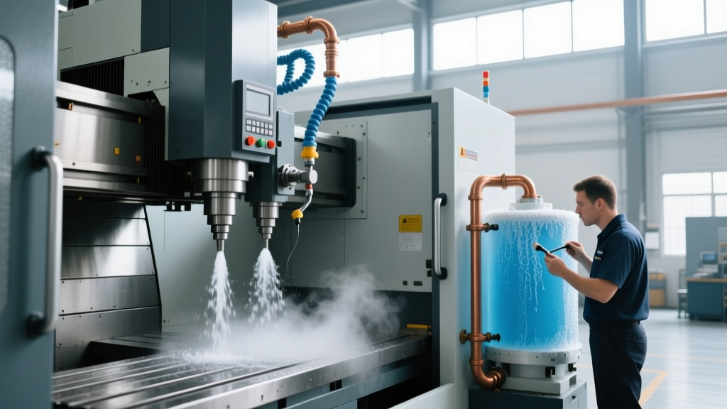
Understanding the thermodynamic footprint of your cooling method is the first step in troubleshooting metrology failures. Flood cooling relies on high thermal mass extraction, while MQL relies on phase-change (evaporative) cooling at the cutting edge. Both introduce distinct thermal failure modes to the machine casting.
| Parameter | Flood Cooling (Central/Unit Chillers) | MQL (Mist) Systems | Metrology Impact & Failure Mode |
|---|---|---|---|
| Heat Extraction | High (Sensible heat transfer via 15-30 GPM flow) | Localized (Latent heat via 5-50 mL/hr evaporation) | Flood failures cause global casting drift; MQL failures cause localized tool/spindle thermal shock. |
| Thermal Equilibrium | 45-90 minutes (Requires full volume temp stabilization) | 5-10 minutes (No bulk fluid loop to stabilize) | Starting metrology tests before flood equilibrium yields false 'warm-up' drift data. |
| Common Fault | Chiller hot-gas bypass valve sticking; TRS sensor drift | Sintered nozzle clogging; air pressure regulator drops | Cyclic pitch errors (Flood) vs. convex ballscrew bowing (MQL). |
| 2026 Repair Cost | $1,800 - $4,500 (Compressor/Valve replacement) | $350 - $1,200 (Generator/Nozzle replacement) | MQL is cheaper to repair but requires stricter daily PM to maintain droplet atomization. |
Symptom-to-Cause Troubleshooting Matrix
Use this decision tree to correlate specific metrology test anomalies with their corresponding coolant system faults.
- Symptom: Cyclic Y-axis pitch error (sine wave pattern) during a 4-hour laser interferometer sweep.
Root Cause: Flood chiller hot-gas bypass valve is stuck partially open, causing a 3°C to 5°C oscillation in the coolant supply temperature as the compressor cycles.
Repair Action: Replace the Sporlan or Danfoss hot-gas bypass valve ($350-$500 part). Do not attempt to clean the internal diaphragm; replace the entire cartridge to ensure ±0.5°C stability. - Symptom: Localized X-axis ballscrew thermal bowing (convex growth of 15-25 µm) during a Renishaw ballbar circular test.
Root Cause: MQL mist nozzle misalignment or partial clog. Dry friction is generating 60°C+ localized heat on the screw shaft because the mist is failing to penetrate the ball nut raceway.
Repair Action: Recalibrate the Unist or Horkos MQL generator air-to-fluid ratio. Remove the sintered bronze nozzles and clean them in an ultrasonic bath with isopropyl alcohol to restore the 5-20 micron droplet size. - Symptom: Spindle Z-axis drift exceeding 15 µm/hr during a static thermal soak test (spindle running at 10k RPM, no cutting).
Root Cause: Spindle oil/coolant chiller TRS (Temperature Regulation System) PT100 sensor calibration drift, causing the chiller to overcool the spindle housing, inducing negative thermal contraction.
Repair Action: Swap out the PT100 RTD sensor ($85 part) and recalibrate the Advantage Engineering or MTA chiller controller setpoint to exactly 20°C (68°F).
Deep Dive: Diagnosing Flood Chiller Degradation (2026 Refrigerant Standards)
As of 2026, the EPA's AIM Act has heavily restricted the use of high-GWP refrigerants like R-410A in new industrial chillers, pushing manufacturers toward R-454B and R-32. If your legacy R-410A chiller is failing to hold the critical 68°F (20°C) ± 0.5°F setpoint required for ISO 230 testing, do not simply top off the refrigerant. Connect manifold gauges and check superheat and subcooling. A normal R-410A system should show 240 PSI head pressure at 95°F ambient and 10-15°F superheat. If head pressure is spiking to 300+ PSI, the condenser micro-channel fins are choked with aerosolized tramp oil from the machine shop environment. Power wash the condenser coils with a low-alkaline degreaser; a 15% drop in heat rejection efficiency is enough to cause the thermal drift that fails a ballbar test.
Deep Dive: MQL System Pneumatic and Capillary Faults
MQL systems do not extract bulk heat from the machine casting; they prevent heat generation at the source. If your metrology tests show tool deflection and localized workpiece distortion, check the pneumatic supply. MQL requires a strict 4 to 6 bar (58-87 PSI) air supply to atomize the biodegradable ester oil. If the SMC or Numatics air regulator diaphragm is fatigued and pressure drops below 3.5 bar, the fluid coalesces into large beads (100+ microns). These beads fail to vaporize in the cutting zone, resulting in fluid pooling, poor lubrication, and massive friction-induced thermal shock. Install a digital inline pressure gauge with a peak-hold memory at the MQL generator inlet to verify pressure stability over a 30-minute cycle.
Step-by-Step Repair: Recalibrating the Coolant Loop for ISO 230 Compliance
Follow this exact sequence to prepare your machine tool's coolant system prior to a metrology certification audit.
- Baseline Thermal Soak: Mount a Renishaw QC20-W ballbar or API Radian laser. Run the spindle at 75% of max RPM and cycle all axes at 50% rapid traverse for 45 minutes. Record the asymptotic thermal growth curve. If Z-axis growth exceeds 25 µm before plateauing, your chiller flow rate is insufficient.
- Coolant Fluid Analysis: Check the flood coolant with a digital refractometer. Tramp oil infiltration alters the specific heat capacity of water-soluble coolants. If Brix concentration exceeds 10% or tramp oil exceeds 2%, the fluid's thermal transfer efficiency drops by up to 18%. Skim the tank and adjust concentration to 6-8%.
- Flow Rate Verification: Clamp an ultrasonic flow meter onto the PEX or polyurethane supply lines feeding the spindle jacket and ballscrew cooling channels. Verify flow matches the OEM spec (typically 3-5 GPM for spindle jackets). A clogged Y-strainer in the chiller loop will drop this to 1 GPM, causing immediate thermal runaway.
- PID Controller Tuning: Access the PLC on the coolant chiller. Tighten the Proportional and Integral bands on the PID loop. A sluggish integral response will allow the coolant temperature to overshoot by 1.5°C during high-load cutting cycles, creating a delayed thermal wave that ruins the volumetric compensation map.
Authoritative References and Standards
For deeper integration of thermal management and metrology standards, consult the following authoritative resources:
- Renishaw Ballbar Diagnostic Guide - Essential reading for interpreting circular contouring errors caused by thermal expansion and servo lag.
- NIST Advanced Manufacturing: Machining and Machine Tools - Comprehensive research on thermal error modeling, compensation algorithms, and the thermodynamic impact of cutting fluids on volumetric accuracy.