Machine Tool Technology Degree Focus: Linear vs Box Way Systems
Explore linear vs box way systems in our machine tool technology degree guide. Compare damping, speed, and load specs for CNC machining.
The Kinematics of Machine Tool Way Systems
A rigorous machine tool technology degree goes far beyond basic G-code programming and CAD/CAM toolpath generation. At the advanced curriculum level, students and practicing engineers must master the structural kinematics of the machine itself. The interface between the moving carriage and the stationary bed—the way system—dictates the machine's ultimate capability regarding chatter resistance, rapid traverse speeds, and geometric accuracy under thermal and mechanical loads.
While marketing brochures often oversimplify the choice between linear guide rails and traditional box ways, the reality is rooted in complex tribology and structural dynamics. Understanding the exact engineering trade-offs between these two systems is critical for specifying equipment in 2026, whether you are outfitting a high-speed aerospace aluminum cell or a heavy-duty titanium roughing room.
Curriculum Note: The Damping Ratio (ζ)In machine tool dynamics, the damping ratio determines how quickly vibrational energy (chatter) dissipates. Sliding friction inherently provides higher damping than rolling friction. This fundamental physics principle is the primary driver behind the ongoing debate between box ways and linear guides in heavy cutting applications.
Box Ways: Sliding Friction and Hydrostatic Engineering
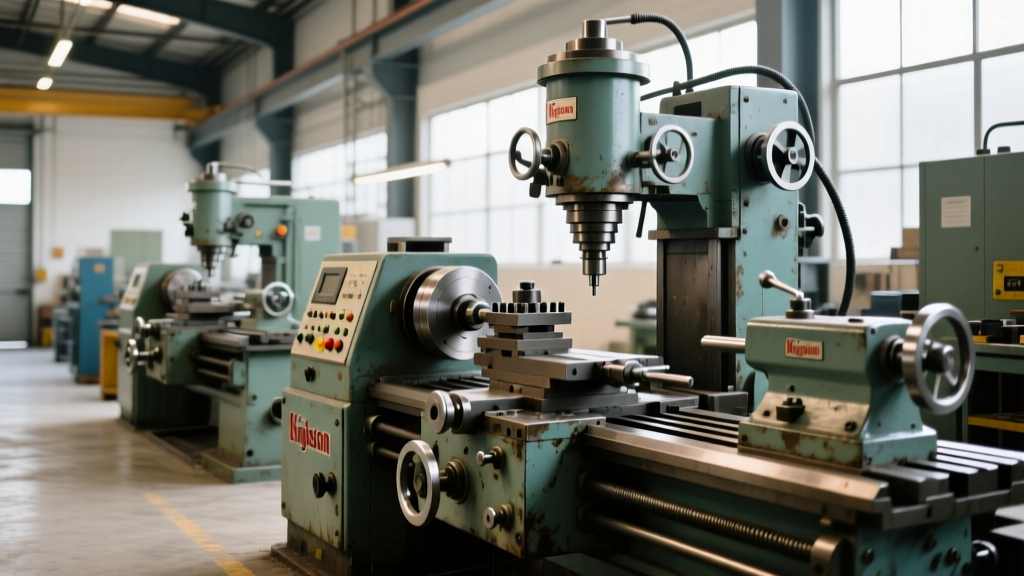
Box ways (or slideways) rely on sliding contact between two large surface areas, typically cast iron on cast iron, or cast iron on a polymer composite. The massive surface area contact provides exceptional structural rigidity and vibration absorption.
Tribology and Hand Scraping
To prevent catastrophic galling and ensure geometric alignment, the mating surfaces of a box way system are meticulously hand-scraped. Master machinists use a master flat and Prussian blue dye to achieve a specific bearing point density. For high-precision jig borers and vertical machining centers, the standard is 20 to 30 bearing points per square inch (BPSI). These microscopic pockets retain lubricant and prevent metal-to-metal contact at startup.
Modern box ways frequently utilize Turcite-B or Moglice (an epoxy-granite composite) on the moving member. These materials lower the coefficient of friction (μ) to approximately 0.05 and eliminate the stick-slip phenomenon that plagues raw cast iron at low feed rates (under 50 mm/min).
Hydrostatic Way Systems
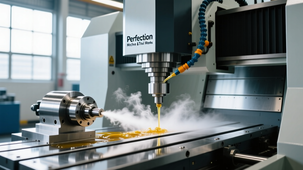
For ultra-heavy cutting, hydrostatic box ways represent the pinnacle of machine tool technology. A high-pressure pump (typically operating between 1,000 and 3,000 PSI) forces oil into pockets machined into the way surface. This creates a fluid film thickness of 0.0002 to 0.0005 inches, completely separating the metal surfaces. Because there is zero metal-to-metal contact, hydrostatic ways exhibit virtually infinite wear life and a damping ratio (ζ) of up to 0.15, making them the undisputed choice for machining Inconel and titanium alloys.
Linear Ways: Recirculating Elements and High-Speed Kinematics
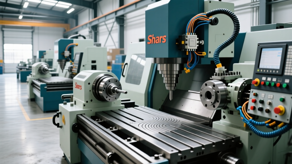
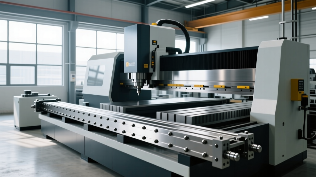
Linear guide systems, dominated by manufacturers like THK, NSK, and Rexroth, utilize recirculating ball or roller bearings housed in a carriage block that rides on a precision-ground profile rail. According to THK LM Guide Technical Specifications, modern linear systems achieve rolling friction coefficients as low as μ = 0.003, which is roughly 1/50th the friction of traditional sliding ways.
Ball vs. Roller Recirculation
Not all linear guides are created equal. The contact geometry dictates the load capacity and rigidity:
- Recirculating Ball Guides: Feature point contact between the ball and the raceway. They offer the lowest friction and highest speeds (up to 120 m/min) but yield under heavy interrupted cuts due to lower static rigidity.
- Recirculating Roller Guides: Utilize cylindrical rollers for line contact. This increases the contact area by a factor of 10 to 100 compared to balls, yielding up to 200% higher rigidity and significantly higher load capacities, bridging the gap toward box way performance while maintaining high traverse speeds.
The Critical Role of Preload
Linear ways require internal preload to eliminate clearance and increase rigidity. Preload is achieved by using oversized rolling elements. In a machine tool technology degree program, students learn to match preload classes to the application:
- Light Preload (approx. 2% of C): Used for high-speed pick-and-place and light aluminum milling. Minimizes heat generation.
- Medium Preload (approx. 8% of C): The standard for general-purpose CNC vertical machining centers (VMCs). Balances rigidity with thermal stability.
- Heavy Preload (approx. 13% of C): Required for heavy-duty steel milling and boring operations. Generates significant heat at high speeds, necessitating specialized grease or oil-air lubrication systems.
Technical Comparison Matrix: Box Ways vs. Linear Guides
The following matrix outlines the hard engineering data separating these two paradigms. This data aligns with testing methodologies outlined in ISO 230-1: Test conditions for metal cutting machine tools regarding geometric and thermal accuracy.
| Engineering Parameter | Box Ways (Sliding / Turcite) | Hydrostatic Ways | Linear Guides (Roller Type) |
|---|---|---|---|
| Damping Ratio (ζ) | 0.05 - 0.08 | 0.10 - 0.15 | 0.002 - 0.005 |
| Max Rapid Traverse | 15 - 30 m/min | 10 - 24 m/min | 48 - 100+ m/min |
| Max Acceleration | 0.3 - 0.5 G | 0.2 - 0.4 G | 1.0 - 2.0 G |
| Static Rigidity | High (Mass dependent) | Extremely High (Film stiffness) | High (Preload dependent) |
| Stick-Slip at Low Speed | Mitigated by Turcite/Way Oil | None (Fluid film) | None (Rolling contact) |
| Maintenance Cycle | High (Scraping, way lube checks) | Very High (Filtration, pump service) | Low (Grease/Oil-air intervals) |
Decision Framework: Matching Way Systems to the Workpiece
Selecting the correct way system is not about finding the 'best' technology, but rather matching the machine's dynamic response to the specific chip-formation mechanics of the target material.
Application Matrix:- Aerospace Titanium (Ti-6Al-4V) & Inconel 718: Low cutting speeds (30-60 m/min) but massive cutting forces and high chatter risk. Prescription: Box ways or Hydrostatic ways. The high damping ratio absorbs the low-frequency vibrations inherent in machining high-strength superalloys.
- Mold & Die (P20 / H13 Tool Steel): Requires a mix of heavy roughing and high-speed finishing. Prescription: Heavy-preload Linear Roller Ways. They provide sufficient rigidity for roughing while allowing the 30+ m/min feed rates needed for 3D contouring.
- Aluminum 6061-T6 / 7075 & Composites: High-speed machining (HSM) with low cutting forces but high spindle speeds (20,000+ RPM). Prescription: Linear Ball Ways. The low friction and high acceleration (1.5G+) minimize non-cut time and allow the machine to keep up with high-feed CAM toolpaths.
Failure Modes and Preventative Maintenance
Even the most advanced way systems will fail if maintenance protocols are ignored. Understanding failure modes is a core competency for any machine tool technician.
Box Way Failure: Stick-Slip and Scoring
If the dedicated way lubrication system fails, or if the wrong oil is used, the boundary lubrication film collapses. This results in stick-slip (jerky motion at low feeds) and eventually severe scoring of the cast iron. Actionable fix: Always use an ISO VG 68 way oil containing specific tackifiers (such as molybdenum dialkyldithiocarbamate) and friction modifiers. Never substitute standard hydraulic oil (ISO VG 32/46), as it lacks the adhesive properties required to stay on vertical way surfaces under gravity.
Linear Way Failure: Brinelling and Carriage Seizure
Linear guides are highly susceptible to shock loads. Dropping a heavy vise onto the table, or crashing the spindle, can cause Brinelling—permanent indentations in the raceway caused by the rolling elements. Once Brinelling occurs, the carriage will exhibit a distinct 'bump' every time a ball or roller passes the dent, destroying surface finish quality. Furthermore, if the way covers (bellows) are torn, cast iron chips will enter the recirculation end-caps, jamming the carriage. Actionable fix: Inspect way wipers and bellows weekly. Replace end-seals immediately if they show wear, and utilize oil-air mist lubrication for high-duty cycles to flush debris from the raceway.
'The choice between linear and box ways ultimately defines the machine's personality. You cannot force a linear-way VMC to aggressively hog out titanium without catastrophic chatter, just as you cannot expect a heavy box-way horizontal boring mill to achieve the contouring speeds required for aluminum aerospace structures. Match the kinematics to the metallurgy.'
— Advanced Machine Tool Dynamics Seminar, 2025
Summary
Mastering the technical specifications of machine tool way systems is what separates a basic operator from a true manufacturing engineer. By analyzing the damping ratios, friction coefficients, and preload dynamics of both box ways and linear guides, shops can optimize their capital equipment investments, drastically reduce cycle times, and eliminate chatter-induced scrap rates.