Linear vs Box Ways: Which Best Supports Machine Tool Automation?
Compare linear and box way systems to determine which foundation best supports your machine tool automation, robotic tending, and payload needs.
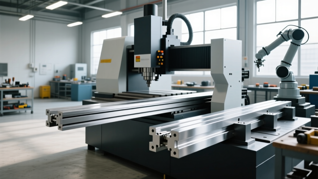
Integrating robotic part loaders, automated pallet changers (APCs), and gantry systems into a machining cell exposes the physical limits of the machine tool itself. While machine tool automation software and robotics dictate cycle sequencing, the machine’s way system—specifically the choice between linear guideways and traditional box ways—dictates the physical speed, payload capacity, and vibrational stability of the automated process. Selecting the wrong way foundation for a specific automation profile results in either catastrophic chatter during heavy automated cuts or unacceptable non-cutting traverse times in high-speed robotic tending.
The Automation Bottleneck RealityA Fanuc or KUKA robot can load a raw casting in 4.5 seconds. If that machine tool utilizes box ways limited to 20 m/min rapids, the axis traverse to the cut zone adds 12 seconds of dead time. Conversely, if a linear-way machine attempts an automated, heavy interrupted cut on that same casting, the lack of damping will trigger harmonic chatter, destroying the spindle bearings and scrapping the part. The way system must match the automation's mass and speed profile.
Linear Guideways: The Speed Advantage for Robotic Tending
Linear guideways utilize recirculating ball or roller bearings running on hardened steel rails. This rolling contact yields a friction coefficient of approximately 0.002, virtually eliminating the stick-slip effect during slow, automated contouring operations. According to technical data from THK's linear motion engineering specifications, modern high-load roller guides can sustain massive static loads while permitting rapid traverse rates between 40 m/min and 60 m/min.
Optimal Automation Scenarios for Linear Ways
- High-Mix, High-Volume Robotic Tending: Machines like the Brother Speedio or Fanuc RoboDrill series utilize linear ways to achieve 50+ m/min rapids. When paired with a 6-axis robot, the machine's rapid axis positioning ensures the spindle is at the part before the robot's gripper has even fully retracted.
- Light-to-Medium Payload Gantry Loaders: For automated top-loading gantries handling aluminum or thin-wall steel components (under 150 kg), linear ways provide the acceleration needed to keep pace with the gantry's indexing speed.
- Multi-Axis Simultaneous Interpolation: Automated 5-axis trunnion tables rely on linear guides to maintain precise, friction-free movement during complex, continuous toolpath generation without requiring massive servo torque to overcome sliding friction.
The Damping Deficit
The primary limitation of linear ways in automated cells is their damping capacity. The point contact of recirculating balls provides minimal surface area to absorb vibrational energy. When an automated pallet changer delivers a 2,000 kg titanium aerospace bracket, and the spindle engages in a heavy interrupted cut, the kinetic energy transfers directly into the linear blocks, causing micro-deflections and premature carriage failure.
Box Ways: The Damping Imperative for Heavy Automated Machining
Box ways feature a sliding contact design where the moving axis glides directly over the stationary base, typically lined with a low-friction polymer composite like Turcite-B or Moglice. This massive surface contact area creates a friction coefficient of roughly 0.05 (for sliding ways), but it provides a damping capacity that is 3 to 5 times greater than linear guideways. For hydrostatic box ways, which separate the surfaces with a pressurized oil film, friction drops to near-zero (0.001) while maintaining maximum damping.
Optimal Automation Scenarios for Box Ways
- Heavy-Payload APC Integration: Horizontal machining centers (HMCs) equipped with automated pallet pools—such as the Makino a61nx or Okuma MA-H series—frequently utilize box ways (or heavily oversized roller linear guides that mimic box way geometry) to absorb the shock of loading massive tombstones and dense castings.
- Automated Hard Milling and Interrupted Cuts: When a lights-out manufacturing cell machines hardened tool steel (60+ HRC) overnight, the extreme cutting forces generate high-frequency vibrations. Box ways absorb this energy, preventing the tool deflection that would otherwise trigger a broken-tool alarm and halt the automated cell.
"In heavy-duty automated machining, rigidity is not just about static stiffness; it is about dynamic damping. Box ways act as a massive mechanical low-pass filter, absorbing the high-frequency chatter that destroys spindle life in unattended operations."
Head-to-Head Specification Matrix for Automated Cells
When designing a machine tool automation layout, use the following engineering matrix to align the way system with your robotic and payload requirements.
| Engineering Metric | Linear Guideways (Ball/Roller) | Box Ways (Sliding / Turcite) | Hydrostatic Box Ways |
|---|---|---|---|
| Friction Coefficient | 0.002 (Rolling) | 0.05 - 0.10 (Sliding) | ~0.001 (Fluid Film) |
| Max Rapid Traverse | 40 - 60+ m/min | 15 - 25 m/min | 30 - 40 m/min |
| Vibration Damping | Low (Point/Line Contact) | High (Full Surface Contact) | Very High (Oil Squeeze Film) |
| Moment Load Capacity | Moderate (Requires wide stance) | Excellent (Inherent geometry) | Excellent |
| Automation Best Fit | High-speed robotic tending (<200kg) | Heavy APCs, interrupted cuts (>1000kg) | Ultra-precision automated boring/milling |
| Relative Machine Cost | Baseline | +20% to +35% | +50% to +100% |
Real-World Integration: Gantry Loaders and Off-Axis Moments
A frequently overlooked factor in machine tool automation is the physical integration of overhead gantry loaders. When a gantry drops a 400 kg raw forging onto the machine table, the impact creates massive off-axis moment loads (pitch, yaw, and roll).
Standard linear guideways resist moment loads poorly unless the rails are spaced exceptionally wide apart or oversized carriage blocks are used, which increases friction and cost. Box ways, by their very geometric nature, envelop the guide rail. The sliding surfaces are positioned far from the axis centerline, providing immense resistance to overturning moments. If your automated cell relies on a top-loading gantry system rather than a side-loading articulated robot, box ways offer a distinct mechanical advantage in maintaining geometric alignment over thousands of automated load cycles.
Maintenance Realities in Lights-Out Manufacturing
Automated cells frequently run unattended on third shifts. The way system dictates the failure modes that can halt production at 3:00 AM.
Linear Way Failure Modes
Linear guides are highly susceptible to coolant and chip ingress. If the automated machine utilizes high-pressure through-spindle coolant (TSC) at 1,000 PSI, fine metallic particles can bypass the carriage end seals. Once inside the recirculation path, these particles dent the raceways, leading to catastrophic block failure. Actionable requirement: For linear-way machines in automated wet-machining cells, specify upgraded heavy-duty scrapers and double-lip urethane seals from the OEM.
Box Way Failure Modes
Box ways rely entirely on a continuous film of way lubricant. If the automated machine's lube pump fails, or if the metering units clog with degraded oil, the Turcite lining will rapidly gall and score the cast iron base. Furthermore, box ways require manual or highly precise CNC scraping during assembly to ensure flatness. Actionable requirement: Integrate flow-sensors on individual way-lube metering units within the machine's PLC to trigger an automated cell-halt before dry-running occurs.
Decision Framework: Selecting the Way System for Your Cell
Use this step-by-step logic flow to finalize your machine tool specification before signing the automation integrator contract:
- Calculate the Maximum Automated Payload: If the combined weight of the fixture, tombstone, and raw material exceeds 800 kg, and the material requires heavy interrupted cuts (e.g., steel forgings, titanium), default to Box Ways to prevent chatter and axis deflection.
- Evaluate the Non-Cut Time Ratio: If the automation profile involves high-mix, low-volume parts where the robot changes parts every 45 seconds, and the machining cycle is under 2 minutes, the rapid traverse speed is critical. Default to Linear Ways to minimize axis positioning time.
- Analyze the Loading Mechanism: If utilizing an overhead gantry loader that drops parts vertically onto the table, prioritize the moment-load resistance of Box Ways. If utilizing a side-loading 6-axis robot or a standard pallet pool, Linear Ways are perfectly adequate.
- Assess Coolpress Pressures: If the automated process requires 1,000+ PSI coolant to clear deep-hole chips, heavily scrutinize the linear way seal options, or pivot to Box Ways which are inherently less sensitive to fine particulate ingress in the sliding interface.
The intersection of way mechanics and automated material handling defines the true throughput of a manufacturing cell. By matching the tribology of the way system to the specific mass, speed, and cutting forces of your automation profile, you eliminate the mechanical bottlenecks that limit ROI in modern lights-out machining.