Mastering CNC Machine Tools: Interlock & E-Stop Training
Train operators on CNC machine tools safety interlocks and E-stop protocols. Learn ISO 13849 standards, stop categories, and bypass prevention.
Severe injuries on the shop floor rarely stem from unpredictable machine failures; they almost always trace back to bypassed safety interlocks or a fundamental misunderstanding of emergency stop (E-stop) physics. When training operators on modern CNC machine tools, safety cannot be reduced to a generic 'push the red button' briefing. Operators must understand the electromechanical realities of safety circuits, the inertia of high-mass spindle assemblies, and the strict architectural requirements of ISO 13849-1.
According to OSHA standard 1910.212, all machine guarding and point-of-operation interlocks must be rigorously maintained and never defeated. Yet, the gap between compliance and shop-floor reality is where accidents happen. This guide provides a deep-dive technical framework for training operators and maintenance technicians on the actual mechanics of machine tool safety systems.
CRITICAL WARNING: The Inertia TrapThe most dangerous misconception among novice operators is that hitting the E-stop instantly freezes the machine. On a standard vertical machining center (VMC) with a 10,000 RPM spindle and a heavy 8-inch chuck, a Category 0 stop cuts power immediately, but rotational inertia will cause the spindle to coast for 4 to 12 seconds. Opening the enclosure door before the spindle reaches absolute zero RPM is a fatal error. Training must physically demonstrate this coast-down time with the door open during a supervised, non-cutting dry run.
Decoding IEC 60204-1 Stop Categories
Operators must know exactly what happens electrically and mechanically when they trigger a stop command. IEC 60204-1 defines three primary stop categories, and modern CNC controls (like Fanuc 31i or Siemens Sinumerik ONE) utilize these differently based on the machine's mass and braking capabilities.
| Category | Electrical Action | Mechanical Result | Operator Protocol |
|---|---|---|---|
| Cat 0 | Immediate power removal (uncontrolled). | Coast to stop. Relies on mechanical friction/brakes. | Mandatory for E-stops. Wait for full coast-down before opening doors. |
| Cat 1 | Controlled stop, then power removed. | Drive decelerates spindle/axes rapidly, then cuts power. | Used for standard Cycle Stops. Prevents tool marking on the workpiece. |
| Cat 2 | Controlled stop, power maintained. | Holding brakes engage; drives remain powered to hold position. | Used for Feed Holds. Never use for personnel entry or E-stops. |
Interlock Evolution: From Mechanical Tongues to RFID
Historically, machine tool doors relied on mechanical tongue-and-groove interlocks (e.g., Schmersal AZ 15/16 series). While robust, these are highly susceptible to physical defeat. An operator can easily jam a spare piece of metal or a zip-tie into the actuator slot to bypass the door switch, allowing the machine to cycle while the enclosure is open.
The Shift to Coded RFID Sensors
To combat bypassing, modern CNC machine tools now utilize non-contact RFID interlocks, such as the Euchner CTM or Schmersal AZM40. These devices use a coded transponder embedded in the door actuator. The sensor reads the unique cryptographic code of the actuator; if an operator attempts to bypass the system with a standard magnet or a piece of steel, the safety relay will not energize.
Training Point: Operators must be taught that if an RFID interlock fails to read, it is almost never a 'glitch' that can be fixed by slamming the door harder. It usually indicates a misalignment exceeding the 3mm tolerance, a damaged transponder, or debris blocking the sensor field. Maintenance must be called immediately, not bypassed.
Performance Level (PL) Architecture:Under ISO 13849-1, safety interlocks on CNC machining centers are typically required to meet Performance Level 'd' or 'e'. This mandates a Category 3 or 4 architecture, meaning the interlock wiring is dual-channel. If one wire is severed or shorted, the safety relay detects the asymmetry and drops the circuit, preventing the machine from starting. Operators should understand that a 'Safety Circuit Fault' alarm usually means a wiring discrepancy, not a software bug.
Daily Interlock Verification Protocol
Relying on annual safety audits is insufficient. NIOSH guidelines on machine guarding emphasize the necessity of routine operator-level verification. Implement this 4-step daily checklist at the start of every first shift:
- The Door Switch Test: With the machine powered on and in 'Memory' mode (but not actively cutting), close the main enclosure door and initiate a spindle start command. Immediately open the door. The spindle command must abort, and the control should trigger a 'Door Open' alarm within 50 milliseconds.
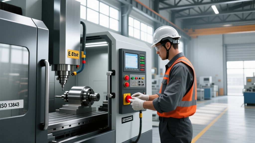
- The E-Stop Circuit Test: Press the primary operator panel E-stop. Verify that the servo drives physically disengage (listen for the contactor 'clunk') and that the coolant and hydraulics pumps shut down. Attempt to clear the alarm and restart the spindle without twisting and releasing the E-stop button; the control must reject the command.
- Tool Changer Arm Interlock: Manually trigger the tool magazine guard switch (if equipped). Attempt to execute a single tool change (e.g., M06 T02). The machine must halt the ATC sequence and throw an enclosure fault.
- Visual Inspection of Actuators: Inspect the door actuators and RFID sensors for heavy coolant buildup, metal swarf accumulation, or physical impact damage. Clean sensors only with isopropyl alcohol and a microfiber cloth—never with abrasive shop rags that can scratch the sensor housing.
Troubleshooting Nuisance Trips vs. Critical Faults
Operators often disable or complain about 'nuisance trips'—interlocks that drop the machine out of cycle seemingly at random. Training operators to differentiate between nuisance trips and critical faults prevents dangerous workarounds.
- Vibration-Induced Nuisance Trips: Heavy roughing operations (like titanium milling) generate massive harmonic vibrations. If mechanical interlocks are worn, the vibration can cause the internal contacts to bounce for microseconds, dropping the safety relay. Fix: Maintenance must replace the actuator and adjust the door hinges to eliminate play.
- Thermal Expansion Trips: On large gantry mills, the morning warm-up cycle can cause the steel enclosure to expand, pulling the door actuator out of alignment with the sensor. Fix: Recalibrate the sensor gap to the manufacturer's specified 5mm to 8mm range.
- Critical Faults (Asymmetry): If the control displays a 'Channel Mismatch' or 'Cross Fault' alarm, one of the dual safety channels has failed or been shorted to 24V. Protocol: Lock out the machine immediately. This is a critical failure of the safety architecture.
Cultivating a Zero-Bypass Safety Culture
The most advanced industrial safety systems are useless if shop floor management implicitly tolerates bypassing to meet cycle time quotas. When an interlock slows down a loading process by three seconds, operators will find a way to defeat it unless leadership actively monitors and rewards safety compliance.
"Safety interlocks are not productivity blockers; they are the physical manifestation of the machine's operational boundaries. An operator who defeats an interlock is not saving time; they are borrowing against a catastrophic failure they cannot afford to repay."
— Lead Manufacturing Safety Engineer, Aerospace CNC Division
Effective training on CNC machine tools requires moving beyond basic button-pushing. By educating operators on the physics of stopping, the cryptography of modern RFID interlocks, and the dual-channel architecture of safety relays, you transform them from passive machine users into active participants in shop floor safety. Implement daily verification protocols, strictly prohibit mechanical bypasses, and ensure every operator respects the inertia hiding behind the E-stop button.