Calibrating a Machine for Sharpening Tools: Accuracy & Maintenance
Discover ISO accuracy standards, calibration intervals, and maintenance schedules to keep your machine for sharpening tools cutting within micron tolerances.
The Hidden Cost of Uncalibrated Tool Grinders
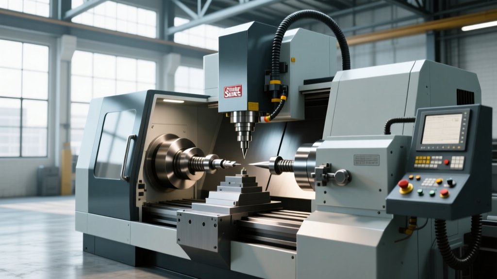
Five-axis CNC tool and cutter grinders represent the pinnacle of subtractive manufacturing precision. When a shop invests in a high-end machine for sharpening tools—such as an ANCA TX7 Linear, a Walter Helitronic series, or a Rollomatic GrindSmart—the expectation is that the machine will hold geometric tolerances under 5 microns. However, without a rigorous, data-driven calibration and maintenance schedule, kinematic drift and thermal deformation will rapidly degrade volumetric accuracy. A poorly calibrated grinding machine doesn't just produce out-of-spec endmills and drills; it causes catastrophic edge chipping in the field, destroys customer trust, and wastes thousands of dollars in carbide blanks and superabrasive wheel packs.
As of 2026, modern tool grinders utilize direct-drive torque motors and linear encoders, but mechanical wear, foundation settling, and ambient temperature fluctuations still necessitate strict adherence to international accuracy standards. This guide details the exact calibration protocols, ISO standards, and maintenance intervals required to keep your tool grinding operations within specification.
Core Accuracy Standards for Sharpening Machinery
Calibration is not a guessing game; it is governed by strict international metrology frameworks. For a machine for sharpening tools, the primary standard governing geometric and volumetric testing is the ISO 230 series (Test conditions for machine tools). Understanding which part of the standard applies to your specific calibration task is critical.
Geometric vs. Volumetric Accuracy
- ISO 230-1 (Geometric Accuracy): Measures the straightness, flatness, and squareness of individual linear axes (X, Y, Z) in a static state. This is your baseline for way alignment and spindle squareness.
- ISO 230-4 (Circular Tests): Utilizes a telescoping ballbar to measure the circular interpolation of two axes simultaneously. This is vital for checking the A-axis and C-axis rotary workheads used for indexing complex tool geometries.
- ISO 230-6 (Volumetric Accuracy): Measures the combined spatial errors of all axes moving simultaneously. Because grinding a helical flute requires 5-axis simultaneous interpolation, volumetric accuracy is the truest indicator of a tool grinder's capability.
Essential Calibration Equipment for Micron-Level Precision
To maintain ISO compliance, shops must invest in metrology equipment capable of sub-micron resolution. Relying solely on the machine's internal probing routines is insufficient for detecting kinematic chain errors.
| Calibration Tool | Primary Application | Approx. Cost (2026) | ISO Standard Addressed |
|---|---|---|---|
| Laser Interferometer (e.g., Renishaw XL-80) | Linear positioning, pitch, yaw, roll, and straightness of X, Y, Z axes. | $45,000 - $65,000 | ISO 230-1, ISO 230-2 |
| Wireless Ballbar (e.g., Renishaw QC20-W) | Circular interpolation, servo mismatch, backlash, and stick-slip on rotary/linear pairs. | $12,000 - $15,000 | ISO 230-4 |
| Laser Tracker (e.g., API Radian) | Volumetric mapping and 5-axis kinematic center point (TCP) calibration. | $80,000 - $120,000 | ISO 230-6 |
| High-Precision Test Mandrel & Dial Indicator | Workhead spindle runout and tailstock alignment verification. | $2,500 - $4,000 | ISO 230-1 (Spindle tests) |
The Definitive Maintenance & Calibration Schedule
A machine for sharpening tools operates in a harsh environment saturated with abrasive carbide dust and grinding oils. Maintenance must be proactive, not reactive. Below is the definitive service schedule to preserve geometric integrity.
Daily Operations (Shift Start)
- Coolant Temperature Verification: Ensure the grinding oil chiller is holding at 20°C ± 0.5°C. Thermal stability of the coolant is just as critical as the ambient room temperature.
- Spindle Taper Cleaning: Use a lint-free cloth and isopropyl alcohol to clean the HSK-A50 or ISO 40 spindle taper. Even a 5-micron carbide dust particle trapped in the taper will cause severe TIR (Total Indicator Runout) on the grinding wheel.
- Wheel Dressing Verification: Inspect the rotary diamond dresser. A worn dresser will cause wheel loading, leading to increased grinding forces and subsequent axis deflection.
Weekly Service Intervals
- Filtration System Audit: Check the grinding oil filtration system. You must use a 10-micron absolute filter (not nominal). Nominal filters allow 30% of particles larger than the rating to pass, which accelerates way cover and ballscrew wear.
- Way Lube Pressure Check: Verify the automatic lubrication system pressure gauge reads within the manufacturer's specified range (typically 1.5 to 2.5 bar). Low pressure leads to stick-slip friction, destroying axis straightness.
Bi-Annual Calibration (Every 6 Months)
"Perform a QC20-W wireless ballbar test on the A-axis and C-axis rotary workheads. Map the reversal spikes and servo mismatch. If the circularity error exceeds 4 microns, adjust the servo loop gains or inspect the direct-drive motor bearings for preload loss."
Annual Overhaul & Volumetric Mapping
- Laser Interferometry: Map the X, Y, and Z linear axes. Update the CNC controller's pitch error compensation tables based on the laser data.
- 5-Axis Kinematic Calibration: Use the machine's integrated probing cycle (or an external laser tracker) to recalibrate the center of rotation for the A and C axes. Mechanical wear shifts the kinematic pivot point over time, causing severe profile errors on complex tool flutes.
- Leveling and Foundation Check: Re-level the machine using a precision electronic level (0.001 mm/m resolution). Foundation settling can induce twist into the machine bed, altering squareness between the Z-axis and the workhead.
Troubleshooting Geometric Drift: A Decision Framework
When finished cutting tools fail final inspection, operators often blindly adjust offsets. Use this diagnostic decision tree to identify the root mechanical cause.
Symptom: Finished Endmill Runout Exceeds 5µm
Step 1: Check the tool holding system. Is the ER collet or hydraulic chuck clean and within spec? (If yes, proceed to Step 2)
Step 2: Indicator the workhead spindle taper. Is TIR > 2µm? (If yes, replace spindle bearings or clean the internal taper mechanism. If no, proceed to Step 3)
Step 3: Check the tailstock/quill alignment. Is the tool blank deflecting under grinding pressure? (If yes, realign the tailstock center to the workhead centerline using a test mandrel.)
Symptom: Chatter Marks on the Tool Flute
Step 1: Verify wheel balancing. Has the grinding wheel been dynamically balanced on the spindle at operating RPM? (If yes, proceed to Step 2)
Step 2: Check axis preload. Perform a ballbar test. Are there reversal spikes indicating lost motion or loose ballscrew thrust bearings? (If yes, tighten thrust bearing locknuts and re-map the axis.)
Optimizing the Environment for Peak Accuracy
No calibration schedule can overcome a poor physical environment. To maximize the ROI on a machine for sharpening tools, the grinding room must be isolated from external thermal and vibrational influences.
- Airflow Management: Do not point HVAC vents directly at the machine casting. Asymmetric cooling causes the cast iron to warp, ruining geometric squareness.
- Vibration Isolation: If the shop floor is shared with heavy stamping presses or large lathes, install active or passive pneumatic vibration isolators beneath the grinder's leveling pads. Ground-borne vibrations will translate directly into surface finish defects on the cutting tools.
- Lighting and Heat: Replace any legacy halogen or incandescent task lighting with LED equivalents. The radiant heat from traditional lighting can create localized thermal gradients on the machine's upper columns.
By treating your tool grinder not just as a production asset, but as a precision metrology instrument, you ensure that every endmill, drill, and reamer produced meets the exacting demands of modern aerospace and medical machining. Adhering to ISO 230 standards and maintaining a strict, data-backed service schedule is the only way to guarantee long-term profitability in the competitive tool grinding sector.