Allied Tool & Machine Co. Calibration Standards & Operator Training
Discover how Allied Tool & Machine Co. trains operators on ASME B5.54 machine tool calibration standards, ballbar testing, and geometric accuracy maintenance.
Geometric drift in CNC machining centers is rarely a sudden failure; it is a cumulative degradation of mechanical tolerances, thermal stability, and servo performance. While metrology labs handle annual laser interferometry certifications, the day-to-day accuracy of a machine tool relies entirely on operator-led calibration verification. Precision-focused facilities like Allied Tool & Machine Co. have built their operational ethos on shifting calibration awareness from the quality inspection room directly to the shop floor, empowering operators to identify, diagnose, and compensate for volumetric errors before they result in scrapped aerospace or medical components.
Decoding the Core Accuracy Standards
Before an operator can maintain accuracy, they must understand the frameworks used to measure it. Training programs modeled after top-tier job shops emphasize familiarity with two primary standards:
- ISO 230-2:2014: The global benchmark for determining the geometric accuracy of machines operating under quasi-static conditions. It defines how to measure linear axis positioning accuracy and repeatability.
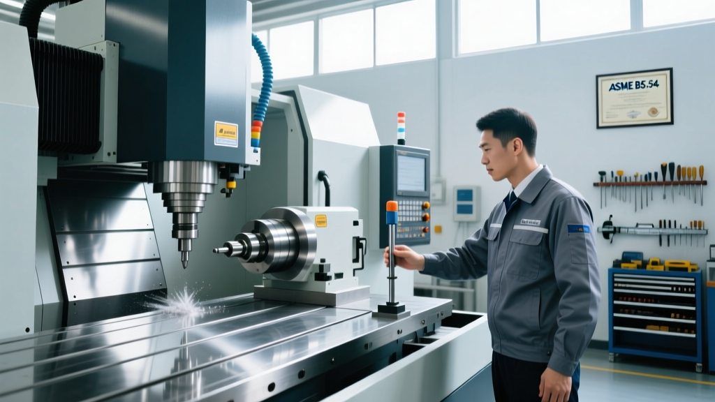
- ASME B5.54: The standard specifically governing methods for the performance evaluation of CNC machining centers, heavily focusing on volumetric accuracy and contouring performance.
Operators do not need to memorize the mathematical formulas for systematic positional deviation, but they must understand how these standards translate to shop-floor realities. For instance, ISO 230-2 dictates that a machine's positioning accuracy must be verified at specific target points along an axis. If an operator notices a consistent 15-micron deviation at the center of the X-axis travel during a test cut, they are witnessing a systematic error that can often be mapped out via the CNC controller's pitch error compensation table, provided the error is repeatable.
The Daily Thermal Stabilization Protocol
The most frequently overlooked variable in machine tool accuracy is thermal growth. Cast iron machine bases and columns expand at a coefficient of approximately 10.4 µm/m·°C, while aluminum workpieces expand at 23.1 µm/m·°C. A 10-degree Fahrenheit fluctuation in a shop environment can easily push a 500mm Z-axis travel out of tolerance by over 50 microns.
The Allied Tool & Machine Co. Warm-Up Mandate:Operators are trained to never run a tight-tolerance first article on a "cold" machine. A standardized 15-minute spindle and axis warm-up program is executed at the start of every shift and after any idle period exceeding 4 hours. This distributes spindle bearing grease, stabilizes the Z-axis ballscrew, and brings the coolant to ambient equilibrium.
A robust warm-up G-code routine should exercise the axes across 80% of their total travel and step the spindle through operational RPM ranges. Here is a baseline template operators use to stabilize a standard VMC:
O9001 (THERMAL STABILIZATION ROUTINE)
G00 G53 Z0. (RETRACT TO HOME)
G00 G53 X500. Y250. (MOVE TO TABLE CENTER)
M08 (COOLANT ON TO STABILIZE TEMP)
M03 S2000
G04 X300. (DWELL 5 MIN)
M03 S4000
G04 X300.
M03 S6000
G04 X300.
M05
M09
M30
Interpreting Ballbar Diagnostics on the Shop Floor
Wireless ballbar systems, such as the Renishaw QC20-W, are the gold standard for rapid contouring accuracy checks. While metrologists use laser trackers for deep volumetric mapping, operators use ballbars to catch sudden mechanical faults. Training operators to read a ballbar circularity plot is a critical best practice. The plot translates complex servo and mechanical interactions into visual signatures.
| Plot Signature | Root Cause | Operator Action / Best Practice |
|---|---|---|
| Ovality (Tilted 45°) | Squareness error between X and Y axes. | Verify foundation leveling; check anchor bolts. Call maintenance if tram is out. |
| Figure-Eight Pattern | Backlash or lost motion in axis ballscrews. | Check thrust bearings; update backlash compensation parameters in the CNC control. |
| Hash Marks / Spikes | Stick-slip friction or damaged linear guideways. | Clean and re-lube way covers; check for way lube system blockages. |
| Clovers (Multi-lobed) | Servo mismatch or cyclic ballscrew pitch error. | Check servo drive tuning parameters; inspect ballscrew for localized wear. |
By equipping operators with the knowledge to identify a "figure-eight" plot as backlash rather than a programming error, shops drastically reduce the time spent troubleshooting scrapped parts. The operator can immediately pause production, measure the backlash with a dial indicator, and input the precise compensation value into the machine's macro variables.
Environmental Controls and Coolant Management
Calibration is not just about the machine's mechanics; it is about the fluid and air surrounding it. According to precision engineering guidelines from NIST, thermal gradients are the leading cause of dimensional instability in high-precision machining.
Coolant Temperature Verification
Operators must treat coolant as a thermal control fluid, not just a lubricant. Best practices dictate that coolant temperature should be maintained within ±1°C (±1.8°F) of the ambient shop temperature (ideally 20°C / 68°F). If the shop is 72°F and the coolant chiller is set to 65°F, the coolant will actively shrink the cast iron machine base and the workpiece, creating phantom thermal errors that mimic geometric miscalibration.
Warning: Crash-Induced Pitch ErrorsIf a machine experiences a moderate to severe crash, operators must never assume the machine is accurate simply because the tool setter probes correctly. A crash often bends the ballscrew slightly or shifts the thrust bearing housing, altering the pitch error map. Following any crash exceeding 50 lbs of estimated impact force, a full ballbar test and a laser pitch error recalibration must be performed before resuming production.
Implementing a Tiered Calibration Response Matrix
To prevent operators from either ignoring minor drifts or overreacting to normal thermal fluctuations, elite manufacturing environments utilize a Tiered Calibration Response Matrix. This framework provides clear, actionable boundaries for shop-floor personnel.
- Tier 1: Operator-Level Compensation (Green Zone)
Condition: Volumetric drift is under 20 microns, or backlash is detected via ballbar.
Action: Operator updates tool wear offsets, verifies workpiece probing routines, and adjusts CNC backlash compensation parameters. Documented in the daily shift log. - Tier 2: Maintenance Intervention (Yellow Zone)
Condition: Ballbar plot shows stick-slip friction, squareness errors exceed 15 µm/m, or way lube pressure drops.
Action: Operator halts tight-tolerance work. Maintenance is dispatched to flush lube lines, re-scrape way inserts, or adjust axis gibs. Machine is re-qualified with a test cut. - Tier 3: Metrology Recertification (Red Zone)
Condition: Laser interferometry reveals non-linear pitch errors, or a crash has compromised the ballscrew thrust bearings.
Action: Machine is locked out. External metrologists are brought in to perform full 21-degree-of-freedom volumetric error mapping and update the controller's spatial compensation tables.
Summary of Operator-Driven Accuracy
Machine tool accuracy standards like ISO 230 and ASME B5.54 are not merely administrative hurdles for annual audits; they are the mathematical language of precision. By adopting the rigorous, operator-centric training methodologies championed by industry leaders like Allied Tool & Machine Co., shops transform their machinists from passive button-pushers into active guardians of geometric integrity. Mastery of thermal stabilization routines, ballbar plot interpretation, and environmental baselines ensures that the machine's certified accuracy is maintained on every shift, not just on the day the calibration technician visits.