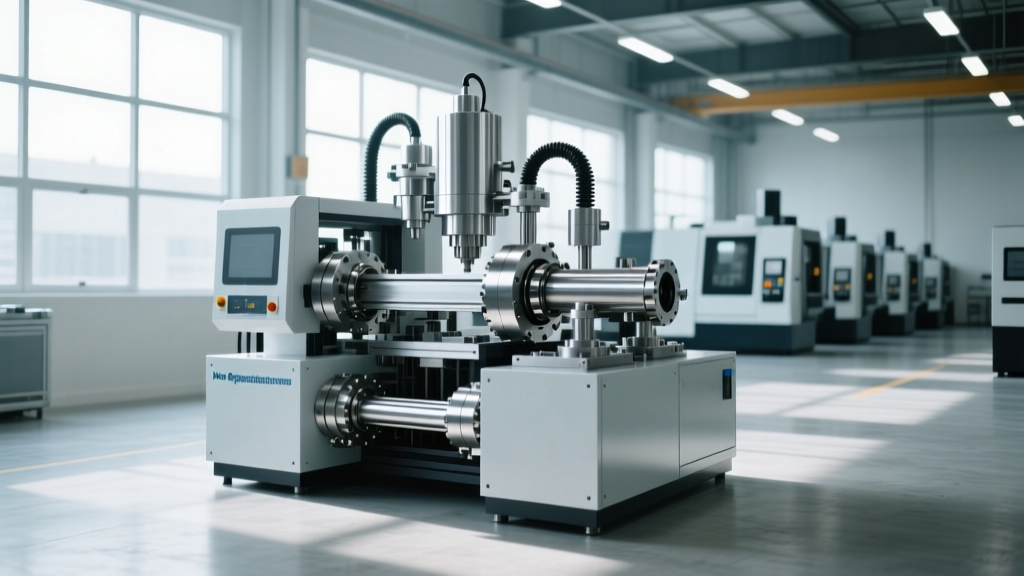
How Regenerative Manufacturing Test Equipment Saves Energy
Explore the technical specs and bidirectional topology of regenerative manufacturing test equipment, cutting EOL testing energy costs by up to 90%.
End-of-line (EOL) testing for high-power electronics, electric vehicle (EV) powertrains, and industrial battery packs traditionally relies on resistive load banks. While effective for validating thermal and electrical limits, resistive testing converts 100% of the tested energy into waste heat. As 800V and 1000V silicon carbide (SiC) architectures dominate 2026 production lines, the thermal and electrical overhead of traditional testing has become unsustainable. Regenerative manufacturing test equipment solves this by utilizing bidirectional power topologies to recover and reuse energy, fundamentally altering the economics and facility requirements of high-power test cells.
The Thermodynamics and Economics of Traditional vs. Regenerative Testing
To understand the engineering shift, consider a standard 500 kW EV inverter test cell. Using a traditional resistive load bank, testing a single unit at full load for a 15-minute cycle generates approximately 106,000 BTUs of waste heat per cycle. In a high-volume plant running three shifts, this continuous heat rejection forces facility engineers to oversize HVAC systems, creating a secondary parasitic energy drain.
Facility Warning: The Hidden HVAC MultiplierFor every 1 kW of resistive heat generated in an enclosed test cell, industrial HVAC systems typically require 0.3 kW to 0.4 kW of additional electrical power to reject that heat. A 500 kW resistive test cell effectively operates as a 650 kW to 700 kW electrical load from the utility's perspective.
Regenerative manufacturing test equipment eliminates this thermal penalty. By employing active front-end (AFE) rectifiers and bidirectional DC-AC inverters, the system routes the power generated by the device under test (DUT) back into the facility's local AC grid or DC microgrid. According to data from the U.S. Department of Energy's Advanced Manufacturing Office, implementing energy-recovery systems in high-power testing environments can reduce localized electrical consumption by up to 90%, aligning directly with modern industrial decarbonization targets.
Cost Breakdown: 500 kW Test Cell (Annualized)
- Resistive Setup: 2,400,000 kWh (Testing) + 720,000 kWh (HVAC) = $374,400/year (at $0.12/kWh).
- Regenerative Setup (90% Efficiency): 240,000 kWh (Make-up power for 10% loss) + 15,000 kWh (Minimal HVAC) = $30,600/year.
- Net Savings: $343,800 per year, per test cell. Payback period for the capital expenditure of regenerative equipment is typically 14 to 18 months.
Inside the Topology: How Bidirectional Power Recovery Works
The core of regenerative manufacturing test equipment is the bidirectional AC-DC-AC matrix. Unlike unidirectional power supplies, this topology allows power to flow from the grid to the DUT (motoring mode) and from the DUT back to the grid (generating or braking mode).
- Active Front End (AFE) Rectifier: The grid-side converter utilizes IGBT or SiC MOSFET switches operating at high frequencies (typically 20 kHz to 50 kHz). This stage converts incoming AC utility power to a stable high-voltage DC bus while maintaining a near-unity power factor (>0.99) and keeping Total Harmonic Distortion (THD) below 2%.
- Common DC Bus: The DC link acts as the energy reservoir. In multi-axis test systems (e.g., testing a dual-motor EV powertrain), the DC bus allows power generated by the braking motor to be directly consumed by the accelerating motor, achieving internal energy recycling before ever interacting with the AC grid.
- Device-Side Inverter: This stage emulates the battery pack or grid environment for the DUT. When the DUT enters a regenerative braking test profile, the device-side inverter seamlessly transitions from a power source to a power sink, pushing the recovered energy back onto the DC bus.
- Grid Synchronization (PLL): A Phase-Locked Loop (PLL) algorithm continuously monitors the facility's grid phase and frequency. The AFE inverts the recovered DC power back into clean AC power, synchronizing it perfectly with the local grid to prevent phase-clashing or voltage sags.
Technical Specification Matrix: Resistive vs. Regenerative ATE
When specifying manufacturing test equipment for a new production line, engineers must evaluate the electrical and physical footprints. The table below contrasts a standard 600 kW resistive load bank with a modern 600 kW regenerative grid simulator.
| Parameter | Resistive Load Bank | Regenerative Grid Simulator |
|---|---|---|
| Energy Recovery Rate | 0% | 85% - 93% |
| Input THD (at full load) | N/A (Linear Load) | < 2% (IEEE 519 Compliant) |
| Power Factor | 1.0 | > 0.99 (Adjustable) |
| Cooling Infrastructure | Forced Air / Water (Rejects 100% heat) | Liquid-to-Water (Rejects <10% heat) |
| Typical Footprint (600kW) | ~45 sq. ft. (Floor standing) | ~12 sq. ft. (19-inch Rack Mount) |
| Voltage Emulation | None (Passive dissipation) | Programmable (Sags, swells, transients) |
Application Deep-Dive: EV Inverter End-of-Line (EOL) Testing
The transition to 800V SiC traction inverters requires test equipment capable of handling extreme dv/dt (voltage rise times) and high switching frequencies. According to NREL's Transportation and Mobility Research division, validating the efficiency maps of these next-generation powertrains requires dynamic load cycling that traditional equipment cannot replicate without massive thermal degradation.
Sizing the DC Link and Managing Harmonics
When integrating regenerative manufacturing test equipment for 800V systems, the DC bus must be rated for at least 1200V to accommodate transient overshoots during hard-switching events. Furthermore, the high-frequency switching of the AFE generates common-mode currents. Engineers must specify integrated common-mode chokes and dv/dt filters within the test equipment to protect the DUT's sensitive gate-drive circuitry from electromagnetic interference (EMI).
"Facility engineers often overlook the upstream transformer when deploying regenerative ATE. Because the AFE injects high-frequency harmonics back into the local grid, standard distribution transformers will overheat. You must specify a K-13 or K-20 rated transformer, or utilize a dedicated isolation transformer with electrostatic shielding to prevent harmonic propagation into the plant's main bus."
Facility Integration: Upgrading Your Test Cells
Retrofitting an existing production line with regenerative manufacturing test equipment requires careful electrical planning. Follow this integration framework to ensure compliance and operational stability:
- Conduct a Harmonic Audit: Before installation, measure the existing THD on your facility's main bus. If baseline THD is already above 4%, adding regenerative ATE could push you out of compliance with the IEEE 519-2022 standard, resulting in utility penalties.
- Implement DC Microgrid Coupling: Instead of feeding all recovered energy back to the AC grid, route the DC bus outputs of multiple test cells into a common 800V DC microgrid. This allows a test cell performing a motoring test to draw power directly from an adjacent cell performing a regenerative braking test, bypassing AC-DC-AC conversion losses entirely and pushing system efficiency past 95%.
- Upgrade Coolant Loop Specifications: While regenerative equipment rejects vastly less heat, the power electronics (IGBT/SiC modules) still require precise thermal management. Specify a closed-loop liquid cooling system utilizing a 50/50 propylene glycol and deionized water mix, maintained at a strict 20°C ± 1°C to prevent condensation on high-voltage busbars.
- Configure Anti-Islanding Protection: Because the equipment feeds power into the grid, it must comply with local utility interconnection standards (e.g., UL 1741). Ensure the ATE's firmware includes active and passive anti-islanding protocols to instantly shut down power export if the local utility grid drops offline.
By replacing passive resistive elements with intelligent, bidirectional power electronics, manufacturers transform their test cells from massive energy liabilities into highly efficient, grid-interactive assets. The technical complexity of specifying AFE topologies and managing harmonic compliance is heavily outweighed by the dramatic reductions in operational expenditure and facility cooling requirements.
Related reading
Optimizing IIoT Sensor Maintenance: Insights from Top Telecommunications Equipment Manufacturers 2025

Manufacturing Equipment Finance: Spare Parts Inventory Training