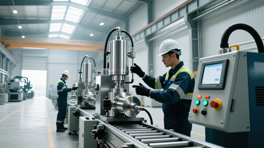
Lean Workstation Specs for a Coating Equipment Manufacturer
Technical specifications and lean design principles for workstations used by a coating equipment manufacturer to assemble precision fluid dispensers.
The Ergonomic and Technical Baseline for Coating Assembly
Designing a lean manufacturing cell for a coating equipment manufacturer requires balancing extreme precision with high-velocity throughput. Unlike standard mechanical assembly, coating and fluid dispensing equipment involves delicate metering valves, PTFE fluid paths, and highly sensitive electronic controllers. The workstation must eliminate micro-vibrations, enforce strict electrostatic discharge (ESD) protocols, and minimize operator reach to prevent repetitive strain.
According to NIOSH guidelines on ergonomics, the primary reach zone for an operator should not exceed a 15.7-inch (400mm) radius from the body's midline. For a coating equipment assembly cell, this means all critical fastening tools, torque controllers, and precision fluid manifolds must reside within this inner hemisphere. Secondary components, such as spare O-rings or bulk tubing, are placed in the extended reach zone (up to 27.5 inches), utilizing gravity-fed flow racks to bring parts forward automatically as bins are emptied.
ESD Callout: Coating equipment often integrates piezoelectric actuators and high-voltage electrostatic spray bells. Workstation surfaces must maintain a surface resistance of 10^6 to 10^9 ohms, strictly complying with ANSI/ESD S20.20 standards. Standard laminates are unacceptable; specify static-dissipative high-pressure laminates (HPL) grounded via a 1-megohm resistor to the facility earth ground.Core Workstation Components & Technical Specifications
A robust lean cell relies on modular framing that allows rapid reconfiguration as coating head designs evolve. The following specifications represent the baseline for a heavy-duty, precision-oriented assembly workstation.
| Component | Technical Specification | Lean Function / Purpose |
|---|---|---|
| Structural Frame | 40x40mm Anodized Aluminum Extrusion (e.g., Bosch Rexroth or 80/20) | Modular reconfiguration; integrates T-slot nuts for tool balancers and monitors without drilling. |
| Work Surface | 1.25-inch thick ESD-safe HPL, 36" x 72" footprint | Prevents static damage to dispensing controllers; provides rigid base for torque reaction. |
| Task Lighting | LED Light Bar, 5000K color temperature, 1200 Lux at surface | High CRI (90+) lighting reveals micro-scratches on fluid seals and coating nozzles. |
| Power Distribution | Overhead articulating arm with 48V DC (tools) and isolated 120V AC (testers) | Separates high-voltage test equipment from low-voltage DC torque drivers to prevent EMI. |
| Height Adjustment | Electric linear actuators, 28" to 46" travel, 1.5"/sec speed | Accommodates 5th to 95th percentile operators; enables sit-stand transitions to reduce fatigue. |
Gravity Flow and Material Handling Integration
Lean manufacturing equipment relies heavily on point-of-use delivery. For a coating equipment manufacturer assembling multi-axis dispensing robots, the bill of materials (BOM) per cell can exceed 150 distinct part numbers. Kanban flow racks must be engineered to specific geometries to prevent part damage.
- Rack Tilt Angle: Set between 15 and 20 degrees. Angles below 15 degrees cause heavy pneumatic cylinders to stall; angles above 20 degrees cause delicate glass fluid sight-gauges to crash into the front retaining lip.
- Roller Track Specs: Use aluminum tracks with 1.25-inch polyurethane-coated wheels spaced at 2-inch centers. Polyurethane prevents the shedding of micro-particles that could contaminate cleanroom-bound coating valves.
- Bin Dividers: Implement adjustable acrylic dividers every 4 inches to separate metric fasteners (M3 to M6) from imperial fluid fittings (1/8" NPT to 1/4" NPT), eliminating cross-threading errors at the source.
Pneumatic and Fluid Routing in Lean Coating Cells
Unlike standard assembly, coating equipment requires live pneumatic and fluid testing at the workstation. Routing these lines without creating tangles or trip hazards is a critical lean design challenge.
- Main Air Supply: Drop a 3/4-inch aluminum mainline from the ceiling grid. Do not use 1/2-inch, as the simultaneous cycling of five test manifolds will cause a pressure drop below the required 85 PSI threshold.
- FRL Integration: Mount a Festo or SMC Filter-Regulator-Lubricator (FRL) unit directly on the left-hand upright of the workstation frame, set to 90 PSI with a 5-micron particulate filter to protect sensitive pilot valves.
- Tool Balancers: Suspend pneumatic torque drivers using zero-gravity balancers (e.g., Tecna or Ingersoll Rand) rated for the exact tool weight plus 10%. This eliminates the operator's lifting effort and keeps air hoses vertically routed.
- Fluid Test Manifold: Integrate a closed-loop solvent flushing system built into the lower shelf. Use 316 stainless steel Swagelok fittings and PTFE-lined hoses to handle aggressive cleaning solvents like MEK or acetone without degrading the workstation plumbing.
Error-Proofing (Poka-Yoke) Sensor Integration
When assembling high-pressure airless spray pumps, a missing $0.50 check-valve spring can result in a $40,000 field failure. Lean workstations must integrate automated verification.
"True lean design does not rely on operator vigilance; it relies on engineered constraints. If a part can be assembled incorrectly, the workstation must physically or electronically prevent the next step." — Bosch Rexroth Lean Production Principles.
For electronic verification, integrate Keyence IV2 series vision sensors mounted on the overhead tool balancer rail. These sensors offer a 1-millisecond response time and can verify the presence and orientation of O-rings before the operator is allowed to trigger the torque driver. Pair this with Banner Engineering K50 pick-to-light modules on the gravity flow racks. The K50 draws less than 50mA per node and communicates via standard IO-Link, allowing the workstation PLC to illuminate only the exact bin required for the current BOM step, reducing pick errors by up to 68%.
Common Failure Modes in Coating Assembly Workstations
Even perfectly designed lean cells degrade over time. Maintenance teams must monitor these specific failure modes common in coating equipment manufacturing environments:
1. ESD Grounding Degradation
Symptom: Intermittent failures in piezoelectric dispensing controllers during final cell testing. Cause: The conductive carbon layer beneath the HPL work surface oxidizes or loses contact with the grounding lug due to workstation vibration. Fix: Implement a daily digital verification log. Use a Monroe Electronics ground resistance tester to verify the path from the surface mat to earth ground remains strictly between 1.0 and 1.5 megohms.
2. Pneumatic Valve Terminal Overheating
Symptom: Solenoid coils on the test manifold burn out prematurely, causing cycle-time delays. Cause: The workstation's enclosure design traps heat generated by continuous 100% duty-cycle testing of coating valves. Fix: Install a 120mm axial fan (40 CFM) at the base of the pneumatic cabinet to create positive pressure and forced convection cooling across the valve terminal blocks.
3. Extrusion Joint Creep
Symptom: The overhead lighting and sensor gantry sags by 2-3 millimeters, throwing off the vision sensor's focal plane. Cause: Standard T-slot nuts loosen under the harmonic vibration of nearby stamping or machining operations. Fix: Replace standard die-cast T-nuts with heavy-duty steel roll-in T-nuts featuring a spring-loaded ball detent, and torque all M8 frame fasteners to exactly 25 Nm using a calibrated digital torque wrench every 90 days.
Cost Analysis and ROI for Lean Cell Implementation
Upgrading from traditional static benches to fully integrated lean manufacturing equipment requires capital justification. Below is a comparative cost matrix for outfitting a single coating equipment assembly cell.
| Investment Category | Traditional Static Bench | Advanced Lean Coating Cell | Delta / Upgrade Cost |
|---|---|---|---|
| Framing & Surfaces | $800 (Steel/Wood) | $2,400 (Aluminum/ESD HPL) | +$1,600 |
| Material Flow Racks | $0 (Floor pallets) | $1,850 (Gravity Kanban) | +$1,850 |
| Pneumatic & Fluid Test Routing | $600 (Basic drop) | $3,200 (Closed-loop/Manifold) | +$2,600 |
| Poka-Yoke & Pick-to-Light | $0 | $4,500 (Vision/IO-Link) | +$4,500 |
| Total Capital Cost | $1,400 | $11,950 | +$10,550 |
While the initial capital expenditure for the advanced lean cell is approximately $10,550 higher per workstation, the return on investment is typically realized within 7 to 11 months. This ROI is driven by a 40% reduction in assembly cycle time (due to eliminated reaching and searching), a 90% drop in fluid-path cross-contamination events, and the elimination of costly field warranty claims caused by missing internal valve components. For a coating equipment manufacturer operating on tight margins and high precision requirements, the technical specifications of the workstation are not just an ergonomic choice—they are a critical component of the product's quality assurance architecture.