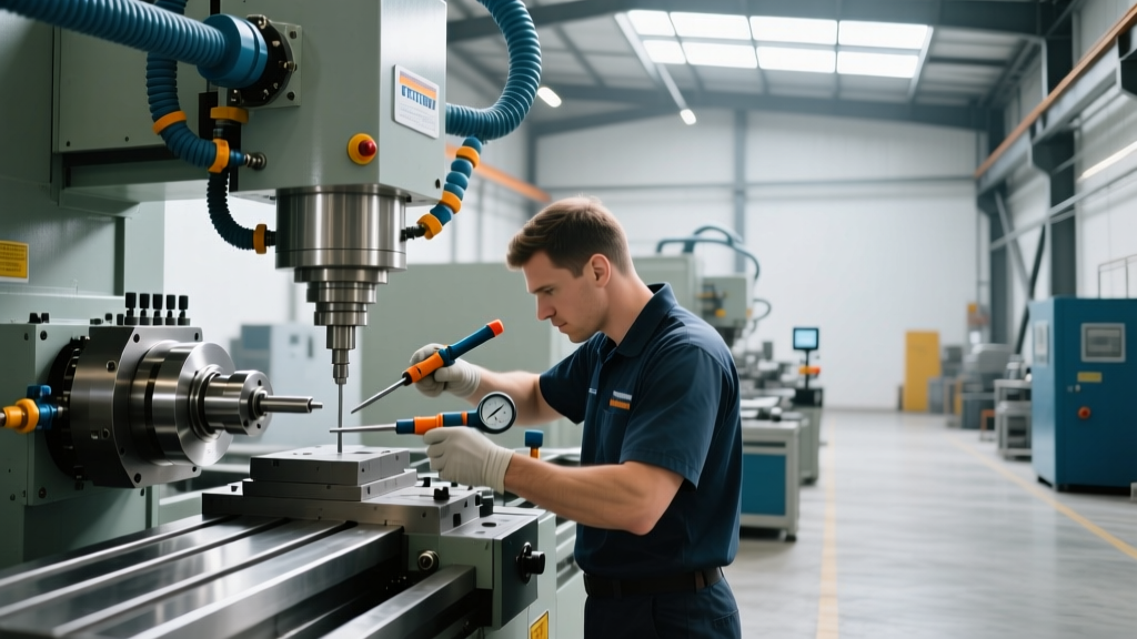
IoT Sensor Training for Custom Industrial Equipment Manufacturing
Master operator training for IIoT sensors in custom industrial equipment manufacturing. Learn calibration, data interpretation, and predictive maintenance.
The Paradigm Shift in Operator Responsibilities
In custom industrial equipment manufacturing, machinery is rarely built with the standardized, out-of-the-box Human-Machine Interface (HMI) ecosystems found in commercial off-the-shelf CNCs or injection molders. When Original Equipment Manufacturers (OEMs) integrate Industrial Internet of Things (IIoT) sensors into bespoke production lines, the operator’s role fundamentally shifts from reactive button-pushing to proactive telemetry analysis. Training operators to interact with retrofitted or custom-designed sensor arrays is no longer optional; it is a critical requirement to prevent catastrophic asset failure and maximize Overall Equipment Effectiveness (OEE).
The Information Gain: A missed vibration alert on a custom-built multi-spindle boring machine can result in $15,000 to $40,000 in spindle replacement costs and 48 hours of downtime. Proper IIoT operator training reduces false-positive alarm fatigue by up to 60%, ensuring that when an alert triggers, operators respond with the correct diagnostic protocol rather than simply resetting the fault code.Core Sensor Technologies and Calibration Protocols
Operators must understand the physical principles behind the sensors monitoring their equipment. Training programs must move beyond "red light means bad" and teach the underlying metrics. The three most critical sensor categories in custom manufacturing environments are vibration, thermal, and proximity/position.
Vibration and Acoustic Emission Sensors
For rotating assemblies in custom machinery, piezoelectric vibration sensors like the Banner Engineering QM42VT2 are industry standards. Operators must be trained to differentiate between velocity (measured in mm/s RMS, indicating overall machine health per ISO 10816 standards) and acceleration (measured in g-peaks, indicating early-stage bearing defects).
Thermal and Infrared Sensors
Custom extrusion dies and specialized welding rigs rely on continuous thermal monitoring. Sensors such as the ifm electronic TN2500 provide continuous process temperature data. Operators must learn to account for emissivity variables when verifying non-contact infrared sensor readings against manual spot-checks using thermal cameras.
| Sensor Category | Common Model Example | Primary Metric | Operator Calibration Check Protocol |
|---|---|---|---|
| Vibration | Banner QM42VT2 | Velocity (mm/s) | Verify mounting torque (2-3 Nm); ensure no debris between sensor base and machine housing. |
| Thermal (IR) | ifm TN2500 | Temperature (°C) | Clean optical window with isopropyl alcohol; verify emissivity setting matches target material. |
| Inductive Proximity | Sick IM18 | Distance (mm) | Check sensing distance with a standardized ferrous test block; inspect for metallic swarf buildup. |
IO-Link vs. Legacy 4-20mA: What Operators Must Know
A major knowledge gap in modern manufacturing training is the distinction between legacy analog signals and smart digital protocols. Many custom machines are currently being upgraded from 4-20mA analog loops to IO-Link (IEC 61131-9).
Operators must be trained on the practical advantages of IO-Link masters, such as the Balluff BNI009. Unlike analog sensors that require a technician with a multimeter to recalibrate, IO-Link allows operators to remotely adjust sensor parameters (like switching a photoelectric sensor from diffuse to retroreflective mode) directly via the HMI. Training must include step-by-step HMI navigation for parameterizing IO-Link devices without opening the electrical enclosure, reducing arc-flash exposure risks in compliance with OSHA electrical safety standards.
Data Interpretation: Moving Beyond Binary Alarms
In custom industrial equipment manufacturing, the HMI is often a bespoke dashboard built on platforms like Ignition or Siemens WinCC. Operators must be trained to interpret trend lines and Fast Fourier Transform (FFT) spectrums rather than just reacting to binary pass/fail indicators.
Reading the FFT Spectrum
When a vibration alarm triggers, the operator should pull up the FFT graph on the HMI. Training should focus on identifying specific fault frequencies:
- 1X Running Speed Peak: Indicates unbalance or misalignment. Action: Schedule laser alignment during the next shift change.
- Non-Synchronous High-Frequency Peaks: Indicates bearing cage or rolling element defects. Action: Prepare for immediate bearing replacement; do not run at full RPM.
- Line Frequency (60Hz/120Hz) Peaks: Indicates electrical issues in the VFD or motor, not mechanical faults. Action: Notify the electrical maintenance team, not the mechanical millwrights.
Troubleshooting Decision Tree for Sensor Anomalies
Operators need a rigid, logical framework to follow when an IIoT sensor throws an anomaly. The following decision tree should be laminated and posted at custom machine workstations:
Anomaly Response Protocol
- Step 1: Verify the Physical Environment. Is there cutting fluid, heavy swarf, or steam obscuring the sensor? If yes, clean the sensor housing using approved solvents and reset.
- Step 2: Check the M12 Connector. Inspect the cable connection. Are the pins corroded or pushed back? Is the cable bent tighter than its minimum bend radius (typically 5x the cable outer diameter)?
- Step 3: Cross-Reference Telemetry. If a thermal sensor reads a spike, does the motor amperage draw on the VFD correlate with the heat increase? If amperage is normal, suspect a failing sensor element.
- Step 4: Isolate the IO-Link Master Port. If multiple sensors on the same machine block drop offline simultaneously, the issue is likely the IO-Link master or the 24V DC power supply, not the individual sensors.
Best Practices for Sensor Maintenance in Harsh Environments
Custom equipment in food processing, pharmaceuticals, or heavy metallurgy operates in extreme environments. Operators are often responsible for the daily washdown or cleaning of these machines, which is where the majority of IIoT sensor failures occur.
The IP69K Thermal Shock Trap: Many operators assume that an IP69K-rated sensor can withstand any cleaning procedure. However, IP69K only certifies resistance to high-pressure, high-temperature washdowns. It does not protect against thermal shock. Spraying 80°C steam directly onto a sensor with a cold optical glass lens will cause micro-fractures, allowing moisture ingress over time. Train operators to maintain a 15-degree offset angle during high-pressure washdowns to protect optical and acoustic sensor membranes.
Furthermore, cable management is a frequent point of failure. Operators must be trained to inspect M12 X-coded (Gigabit Ethernet) and M12 A-coded (IO-Link/Power) connectors for vibrational loosening. Implementing a monthly torque-check schedule using a calibrated torque screwdriver set to 0.6 Nm prevents intermittent data packet loss that can corrupt predictive maintenance algorithms.
Cybersecurity Awareness at the Edge
As custom machines become more connected, the operator is the first line of defense against edge-level cyber vulnerabilities. According to the NIST SP 800-213 guidelines for IoT device cybersecurity, unauthorized physical access to edge gateways (like the Siemens IOT2050) can compromise the entire manufacturing network. Operators must be trained to:
- Never plug unauthorized USB drives into HMI or edge gateway ports for data extraction.
- Recognize the physical signs of a compromised edge gateway (e.g., unexpected LED blinking patterns indicating unauthorized data exfiltration).
- Ensure physical enclosure doors housing network switches and IO-Link masters are locked and sealed at the end of every shift.
Measuring Training Efficacy and ROI
To justify the investment in deep-dive IIoT operator training, manufacturing managers must track specific, quantifiable metrics. Do not rely on generic "completion rates" for training modules. Instead, measure the following KPIs over a 90-day post-training period:
| Metric | Pre-Training Baseline | Target Post-Training | Impact on Custom Equipment |
|---|---|---|---|
| Mean Time to Acknowledge (MTTA) Critical Alarms | 14 minutes | < 3 minutes | Prevents cascading mechanical failures in bespoke assemblies. |
| False-Positive Alarm Reset Rate | 45% of all alarms | < 10% of all alarms | Increases trust in the IIoT system; reduces unnecessary machine stops. |
| Sensor-Induced Downtime (Cleaning/Recalibration) | 2.5 hours / week | < 0.5 hours / week | Directly improves OEE on high-margin custom production runs. |
Aligning with Global IIoT Architectures
Finally, advanced operator training should touch upon how the custom machine they are operating fits into the broader enterprise architecture. Familiarizing lead operators with the concepts outlined in the ISO/IEC 30141 IoT Reference Architecture helps them understand why edge computing (processing data locally on the machine) versus cloud computing (sending data to AWS/Azure) matters. For instance, understanding that vibration FFT processing happens at the edge to save bandwidth helps operators realize why the HMI might show a 2-second delay when pulling historical cloud-based production reports, preventing them from mistakenly assuming the machine’s local control loop is lagging.
By treating operators as intelligent nodes within the IIoT network rather than mere machine tenders, custom industrial equipment manufacturers can unlock the true ROI of their sensor investments, ensuring bespoke machinery runs at peak precision for its entire lifecycle.