Batch vs Continuous Systems in Electrical Equipment Manufacturing
Compare batch vs continuous equipment in electrical equipment manufacturing. Analyze CapEx, OEE, and case studies for switchgear and magnet wire.
Selecting the right production architecture is the most capital-intensive decision in electrical equipment manufacturing. The divergence between batch processing and continuous flow systems dictates factory floor layouts, work-in-progress (WIP) inventory levels, and ultimate unit economics. While batch systems dominate custom, high-mix production like power switchgear and large-scale transformers, continuous systems are non-negotiable for high-volume conductor drawing and printed circuit board (PCB) substrate fabrication.
2026 Production Metrics Snapshot
- Batch System OEE (Overall Equipment Effectiveness): 65% - 78% (Drag from changeovers and WIP staging)
- Continuous System OEE: 85% - 94% (Drag primarily from unplanned maintenance and material threading)
- Average Scrap Rate (Batch): 2.5% - 4.0%
- Average Scrap Rate (Continuous): 0.8% - 1.5% (Concentrated at line start-up and splicing)
Architectural Divergence in Component Production
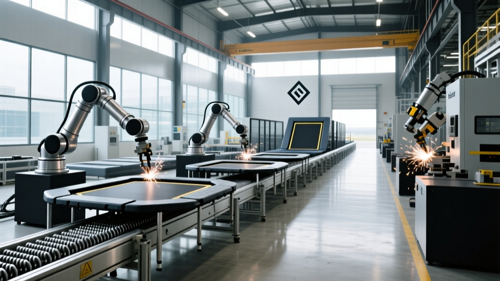
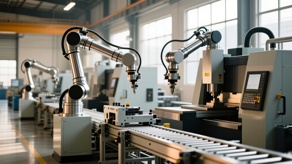
Batch manufacturing equipment processes discrete quantities of components through sequential, often interruptible, stages. In electrical equipment manufacturing, this applies to stamping motor laminations, assembling custom switchgear enclosures, and vacuum pressure impregnation (VPI) of stator windings. The machinery is highly flexible but suffers from idle time during tooling changeovers.
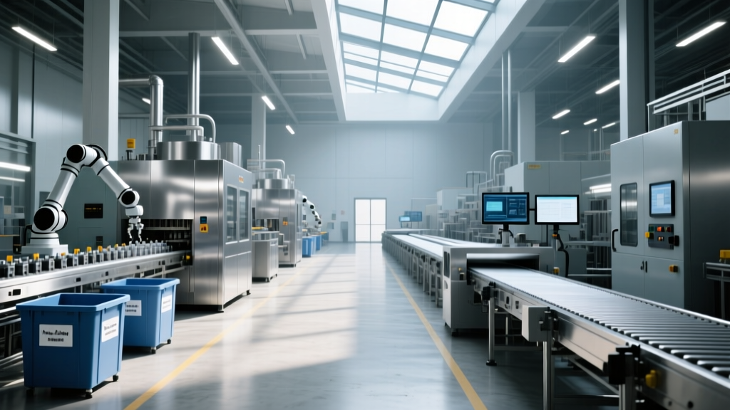
Continuous manufacturing equipment operates on an uninterrupted flow principle, where raw materials enter and finished goods exit without halting the physical or chemical transformation. This architecture is mandatory for magnet wire extrusion, copper rod breakdown, and roll-to-roll (R2R) flexible circuit etching. The machinery demands massive upfront CapEx and is highly inflexible to product specification changes mid-run.
Equipment Specification Matrix
The following matrix contrasts the operational parameters of standard machinery utilized across both paradigms in modern electrical manufacturing facilities.
| Equipment Type | Architecture | Typical Application | CapEx Range (2026) | Changeover / Setup Time |
|---|---|---|---|---|
| CNC Turret Punch (e.g., Amada EM-3610) | Batch | Switchgear enclosures, busbar stamping | $380,000 - $450,000 | 15 - 45 minutes |
| VPI System (Vacuum Pressure Impregnation) | Batch | Transformer coils, motor stators | $1.2M - $3.5M | 4 - 8 hours (cleaning/curing) |
| Multi-Wire Drawing Machine (e.g., Niehoff MMH) | Continuous | Copper/aluminum magnet wire | $1.5M - $2.8M | 12 - 24 hours (full re-thread) |
| Roll-to-Roll (R2R) Etching Line | Continuous | Flexible PCBs, RFID antenna substrates | $4.5M - $8.0M+ | 8 - 12 hours (chemistry balancing) |
Case Application 1: Batch Processing in Power Distribution
Manufacturers of medium-voltage switchgear and distribution transformers rely heavily on batch equipment due to the high degree of engineering customization required per client order. A critical bottleneck in this sector is the insulation and encapsulation of windings.
Vacuum Pressure Impregnation (VPI) Systems
VPI is a strictly batch-oriented process. A manufacturer processing 500 kVA to 5 MVA transformer coils will load a batch of stators into an autoclave. The cycle is rigidly timed and cannot be continuous: vacuum is drawn to below 5 mbar for 45 minutes to extract moisture and air pockets, followed by the introduction of epoxy or polyester resin. Pressure is then ramped to 6-8 bar for 90 minutes to force resin into the micro-crevices of the copper windings, concluding with a 4-hour thermal cure at 150°C.
The equipment footprint is massive, and the batch nature means WIP inventory must buffer the curing time. Upgrading to a modern, automated VPI system with multi-tank resin management costs between $1.2 million and $3.5 million. According to guidelines from the DOE Advanced Manufacturing Office, optimizing the thermal mass and resin viscosity control in batch VPI systems can reduce energy consumption per batch by up to 18%, a critical factor given the rising industrial electricity tariffs.
Case Application 2: Continuous Flow in Conductor Production
At the opposite end of the spectrum is magnet wire manufacturing, where copper or aluminum rod is reduced from 8mm down to 0.05mm. This requires continuous flow architecture.
Multi-Wire Drawing and Annealing
The Niehoff MMH series multi-wire drawing machines represent the standard for continuous conductor production. These machines draw up to 16 or 24 wires simultaneously through a sequence of tungsten carbide or polycrystalline diamond (PCD) dies. Unlike batch processing, the material never stops moving. Inline resistance annealing applies precise electrical currents (often exceeding 2,000 Amps) to soften the work-hardened copper in real-time before it reaches the continuous spooling station.
The primary engineering challenge in continuous wire drawing is managing "slip"—the differential speed between the drawing capstans and the wire itself. If slip percentages deviate by more than 2-4%, the wire will either snap (causing a line shutdown requiring hours to re-thread) or suffer surface scoring. Procurement for a high-speed, 24-wire continuous line exceeds $2.5 million, excluding the $80,000+ annual consumable cost for PCD die replacement and synthetic drawing lubricants. Data from NIST Advanced Manufacturing highlights that integrating inline laser micrometers for continuous diameter feedback reduces scrap rates during steady-state operations to below 0.5%.
CapEx, Tooling, and Procurement Realities
The financial modeling for batch versus continuous equipment extends far beyond the base machine cost. Tooling economics fundamentally alter the ROI timeline.
- Batch Tooling: CNC turret punch tooling and progressive stamping dies for electrical laminations typically range from $8,000 to $35,000 per set. The barrier to introducing a new switchgear enclosure design or motor frame size is relatively low, allowing manufacturers to adapt to market shifts within a single fiscal quarter.
- Continuous Tooling & Rigging: Continuous lines require extensive peripheral rigging. A roll-to-roll PCB etching line requires precision tension controllers, automated chemical dosing pumps, and inline AOI (Automated Optical Inspection) cameras. Furthermore, threading a continuous line after a web break can result in 500 to 1,000 meters of scrapped substrate before steady-state tension and chemical equilibrium are restored.
The Decision Framework for Plant Engineers
Specifying the wrong architecture leads to either crippling changeover losses (if continuous is used for high-mix) or uncompetitive unit costs (if batch is used for commodity components). Use the following decision matrix when designing new production cells or expanding capacity.
Architecture Selection Flowchart
- Evaluate Annual Volume vs. SKU Count: If production exceeds 10,000 linear meters or 500,000 discrete units annually across fewer than 5 SKUs, default to Continuous.
- Assess Changeover Tolerance: If customer lead times require daily product specification changes (e.g., custom busbar routing, varied switchgear amperages), Batch equipment with quick-release tooling is mandatory.
- Analyze Material Transformation: Processes requiring uninterrupted chemical reactions (electroplating, continuous resin casting) or thermal equilibrium (inline annealing) must utilize Continuous systems to maintain metallurgical consistency.
- Calculate Scrap Tolerance: If raw material costs exceed 60% of COGS (e.g., silver-palladium contacts, high-purity oxygen-free copper), invest in Continuous systems with closed-loop tension control to minimize start-up scrap.
The Rise of Hybrid Flexible Manufacturing Systems (FMS)
Modern electrical manufacturing increasingly bridges this divide using Hybrid FMS. For example, in EV traction motor production, the continuous casting and rolling of copper rotor bars are fed directly via automated guided vehicles (AGVs) into batch-oriented robotic insertion and TIG welding cells. By utilizing Manufacturing.gov frameworks for smart factory integration, facilities can maintain the high throughput of continuous upstream processes while accommodating the high-mix assembly requirements of downstream batch operations. When specifying new lines in 2026, ensure that PLC (Programmable Logic Controller) architectures support OPC-UA protocols to allow seamless data handoffs between continuous material flow and batch assembly cells.