Cleanroom Troubleshooting for Aerospace Equipment Manufacturers
Expert troubleshooting guide for aerospace equipment manufacturers to diagnose and repair cleanroom HEPA, FFU, and HVAC pressurization failures.
The Cost of Contamination in Aerospace Assembly
For aerospace equipment manufacturers assembling satellite payloads, precision optics, and flight-grade avionics, maintaining ISO Class 7 (Class 10,000) and ISO Class 8 (Class 100,000) environments is a baseline operational requirement. A localized contamination spike or a cascading pressurization failure does not merely trigger an alarm; it risks millions of dollars in hardware and months of schedule delays. According to the NASA Technical Standards Program, particulate and molecular contamination are primary drivers of optical degradation and thermal control surface failures in space-bound hardware.
This technical guide bypasses basic cleanroom theory, providing facility reliability engineers and maintenance technicians with advanced, symptom-driven troubleshooting frameworks for Fan Filter Units (FFUs), HEPA gel-seal banks, and HVAC differential pressure systems.
The 3-Step Contamination Isolation Protocol
When laser particle counters (e.g., TSI AeroTrak 9510) detect an out-of-spec excursion, execute this sequence before touching any HVAC controls:
- Isokinetic Spatial Mapping: Deploy handheld counters to map the plume. If counts spike only near the ceiling grid, suspect an FFU or HEPA breach. If counts are uniform at waist height, suspect a gowning breach or floor-level turbulence.
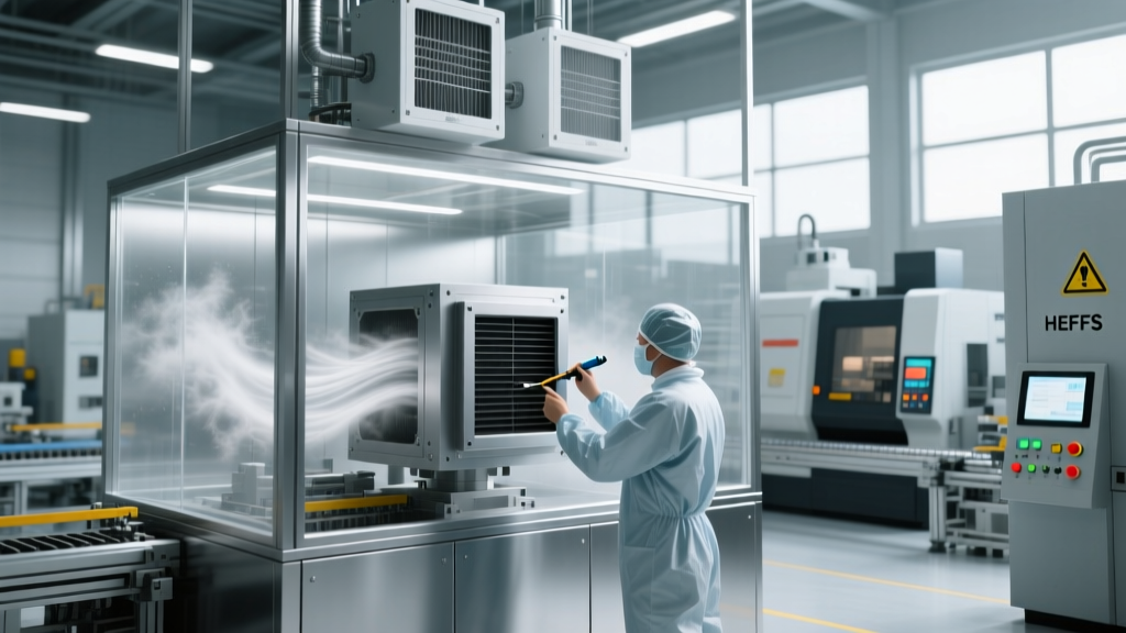
- Airflow Visualization (Smoke Studies): Use ultrapure water vapor or DI water fog generators to visualize laminar flow. Look for 'dead zones' or turbulent eddies around workbenches that indicate unbalanced return air grilles.
- PAO Aerosol Challenge: Introduce Polyalphaolefin (PAO-4) aerosol upstream of the HEPA bank and scan the downstream face and gel-seal track with a photometer to pinpoint micro-leaks.
HEPA and FFU Airflow Failures: Symptom-to-Solution
Modern aerospace cleanrooms rely on modular Fan Filter Units (FFUs) rather than centralized ducted HEPA banks. A typical ISO 7 ceiling utilizes 4-foot by 4-foot FFUs equipped with brushless Electronically Commutated (EC) motors to maintain a strict 90 to 100 feet-per-minute (fpm) downward airflow velocity.
Symptom: Localized Low Airflow Velocity (< 85 fpm)
Root Cause Analysis: EC motor degradation, clogged pre-filters increasing static pressure beyond the motor's torque curve, or a failing speed controller. In 2026, most Tier-1 FFUs utilize closed-loop constant-airflow controllers that rely on differential pressure sensors across the filter media. If the sensor tubing is kinked or disconnected, the controller defaults to a low-speed fail-safe.
Repair Action: 1. Check the Magnehelic or digital differential pressure gauge across the pre-filter. If it reads >0.5 in. w.g., replace the MERV 8 pre-filter pad immediately. 2. Inspect the sensor tubing on the FFU controller board. 3. If the motor draws excessive amperage but produces low airflow, the impeller bearings are seized; replace the motor-impeller assembly.
Symptom: Photometer Leak at the HEPA Filter Perimeter
Root Cause Analysis: Aerospace cleanrooms predominantly use gel-seal HEPA filters (polyurethane gel track) rather than mechanical gaskets to eliminate bypass leakage. Leaks here are rarely caused by the filter media itself; they occur when the gel track is cut, degraded by harsh vaporized hydrogen peroxide (VHP) decontamination cycles, or when the knife-edge frame is misaligned.
Repair Action: Do not attempt to patch a gel seal with silicone caustic. Use a manufacturer-approved gel-melting heat gun and matching polyurethane gel sticks (e.g., Camfil or AAF Flanders repair kits) to reflow and bridge the compromised track. Allow the gel to cure for 4 hours before re-testing.
| Component | Primary Failure Symptom | Diagnostic Tool | Repair Action | Est. Cost (2026) |
|---|---|---|---|---|
| EC Motor Assembly | Low airflow, high heat | Thermal camera, Anemometer | Swap motor/impeller unit | $450 - $680 |
| Gel-Seal HEPA Filter | Particle spike, PAO leak | Photometer, Aerosol generator | Reflow gel track or replace | $1,200 - $2,800 |
| MERV 8 Pre-Filter | High static pressure drop | Differential pressure gauge | Slide out and replace pad | $45 - $85 |
| Constant Airflow Controller | Erratic velocity hunting | Multimeter, BMS network ping | Recalibrate PID or replace PCB | $250 - $400 |
Pressurization and Airlock Interlock Troubleshooting
Aerospace cleanrooms rely on a pressure cascade to prevent ingress of unfiltered air. The core assembly room (ISO 7) must maintain a positive pressure of at least +0.05 to +0.10 inches of water gauge (in. w.g.) relative to the adjacent gowning airlock (ISO 8), which in turn must be positive to the general facility. The Institute of Environmental Sciences and Technology (IEST) strictly outlines these cascading differentials in their contamination control guidelines.
Symptom: Airlock Fails to Maintain Positive Pressure
The Physics of the Failure: Airlocks utilize supply and exhaust dampers modulated by Variable Frequency Drives (VFDs) based on feedback from room-mounted differential pressure transducers (e.g., Dwyer MS-121). If the airlock pressure drops to zero or goes negative when the outer door is closed, the cascade is broken.
Diagnostic Steps:
- Check the Transducer Zero-Offset: Over time, room transducers drift. Open both airlock doors to equalize pressure with the hallway. The Building Management System (BMS) should read exactly 0.00 in. w.g. If it reads +0.02 or -0.01, the sensor requires a zero-point recalibration via its physical span/zero potentiometers or BMS software.
- Inspect Door Sweeps and Gaskets: A pressure drop of 0.03 in. w.g. can be caused entirely by a worn neoprene door sweep dragging on the floor or a degraded magnetic door seal. Replace sweeps annually.
- VFD PID Loop Tuning: If the supply fan VFD is 'hunting' (ramping up and down aggressively), the Proportional-Integral-Derivative (PID) loop gains are too aggressive for the small volume of the airlock. Reduce the Proportional (P) gain by 15% to stabilize the damper actuator.
CRITICAL WARNING: Interlock Bypassing
During HVAC troubleshooting, technicians are often tempted to bypass door magnetic interlocks to keep the supply fans running while doors are propped open. Never bypass interlocks in an aerospace facility. Forcing an outer door open while the inner door is unsealed instantly reverses the pressure cascade, pulling unclassified facility air directly onto sensitive optical benches and composite layup tables. Always use the designated BMS 'Maintenance Mode' which safely locks out inner doors while maintaining exhaust flow.
Air Shower Nozzle Velocity and Alignment Failures
Air showers are the final physical barrier before personnel enter the ISO 7 assembly zone. They must strip particulates from cleanroom garments using high-velocity air jets.
Symptom: Inadequate Particulate Shedding Post-Shower
Root Cause: Air shower nozzles must deliver a minimum velocity of 20 to 25 meters per second (m/s) at the center of the chamber. If velocity drops below 18 m/s, the kinetic energy is insufficient to dislodge 10-micron particles from Tyvek suits. Furthermore, maintenance personnel frequently clean or bump the adjustable nozzles, altering their pitch.
Repair Action: 1. Map the chamber with a hot-wire anemometer. 2. If velocity is low but the blower motor sounds normal, inspect the internal plenum for torn flexible ducting or detached blower wheels. 3. Re-align all nozzles to intersect at the center-axis of the chamber at a 30-degree downward angle, ensuring overlapping turbulence zones across the human profile.
Establishing the Preventative Maintenance Matrix
Reactive repairs in aerospace cleanrooms are a symptom of poor baseline maintenance. Implement the following interval schedule to prevent catastrophic HVAC and filtration failures.
- Weekly: Verify airlock magnetic interlock sequencing and check BMS differential pressure trends for sensor drift.
- Monthly: Inspect return air grilles and floor perforations for obstructions; clean pre-filters in low-traffic zones.
- Quarterly: Perform hot-wire anemometer mapping of 10% of the FFU grid; rotate air shower nozzle alignment checks.
- Bi-Annually: Replace all MERV 8 pre-filters regardless of pressure drop; conduct full PAO HEPA integrity scans on all gel-seal banks.
- Annually: Execute full-room ISO 14644-1 airborne particulate classification testing and smoke visualization studies to recertify laminar flow patterns.
"In aerospace manufacturing, the cleanroom HVAC system is not just facility infrastructure; it is a primary production tool. Treating FFU maintenance with the same rigor as CNC spindle calibration is the hallmark of a mature quality management system."