Troubleshooting Cleanroom Gear in Audio Equipment Manufacturing
Expert troubleshooting guide for cleanroom FFUs, HEPA filters, and ESD systems critical to MEMS and precision audio equipment manufacturing.
The production of high-fidelity micro-acoustic components—specifically MEMS (Micro-Electromechanical Systems) microphones, piezoelectric transducers, and optical laser pickups—requires uncompromising environmental controls. In modern audio equipment manufacturing, a single 5-micron particulate settling on a MEMS acoustic membrane or backplate can cause stiction, shift the resonant frequency, and result in catastrophic Total Harmonic Distortion (THD) failures. Maintaining ISO Class 7 and Class 8 cleanrooms is not just a regulatory hurdle; it is a direct determinant of production yield.
When cleanroom environmental parameters drift, yield loss in audio component fabrication spikes within hours. This guide provides advanced troubleshooting protocols for the critical cleanroom infrastructure that protects precision audio manufacturing lines, focusing on Fan Filter Units (FFUs), pressure cascades, and electrostatic discharge (ESD) mitigation systems.
⚠️ Contamination Alert: Sub-3mm MEMS microphone diaphragms are highly sensitive to outgassing and particulate. Never use standard commercial lubricants on cleanroom door hinges or FFU motor bearings near the audio assembly line. Use only perfluoropolyether (PFPE) based lubricants to prevent volatile organic compound (VOC) contamination on acoustic membranes.Diagnosing Fan Filter Unit (FFU) and HEPA Degradation
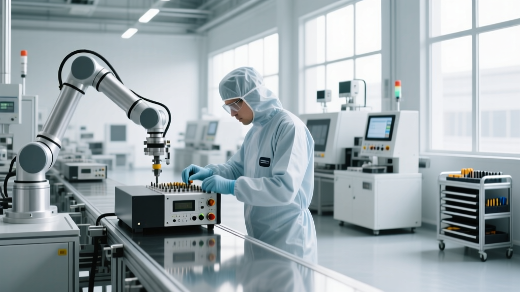
Fan Filter Units provide the laminar airflow necessary to sweep particulates away from exposed audio transducers. The industry standard for cleanroom airflow velocity is 0.45 meters per second (m/s) with a tolerance of ±20%. When particle counters (e.g., Met One 3400) register elevated counts at the workbench level, the FFU array is the primary suspect.
Symptom: Low Airflow Velocity (< 0.36 m/s)
As HEPA filters load with particulate over time, static pressure increases. If your facility uses older PSC (Permanent Split Capacitor) or Shaded Pole motors, airflow will drop as filter resistance rises.
The Fix: Upgrade to ECM (Electronically Commutated Motor) FFUs. ECMs utilize closed-loop feedback to maintain a constant 0.45 m/s velocity regardless of filter loading. If an ECM FFU is underperforming, troubleshoot the motor controller board rather than replacing the entire motor; Hall-effect sensor failures on the controller are the most common cause of ECM RPM drops.
Symptom: Micro-Turbulence and Eddy Currents
Audio assembly benches require perfectly laminar flow. Turbulence traps dust in eddy currents, allowing it to settle on sensitive piezoelectric crystals.
The Fix: Check the FFU diffuser screen. In audio cleanrooms, the perforated aluminum diffuser must be intact. If the filter media has separated from the aluminum frame (a 'gel-seal failure'), localized turbulence will occur. Perform a DOP/PAO aerosol challenge test to verify seal integrity.
Resolving Positive Pressure and Airlock Failures
Audio equipment manufacturing cleanrooms must maintain a positive pressure cascade to prevent unfiltered corridor air from infiltrating the assembly zone. The target differential is typically +0.05 to +0.10 inches of water gauge (in. w.g.) relative to the gowning room, and +0.02 in. w.g. between successive zones.
| Symptom (Magnehelic Gauge) | Probable Root Cause | Corrective Action |
|---|---|---|
| Pressure drops below +0.03 in. w.g. | VAV (Variable Air Volume) damper actuator failure or return air grille blockage. | Recalibrate the Belimo or Johnson Controls actuator; clear obstructions from low-wall return grilles. |
| Pressure spikes above +0.15 in. w.g. | Exhaust fan failure or HEPA filters fully loaded, forcing excess make-up air into the room. | Check exhaust VFDs (Variable Frequency Drives); schedule HEPA filter replacement (typical cost: $400-$600 per 2x4 ULPA filter). |
| Fluctuating pressure readings | Airlock interlock failure allowing simultaneous opening of inner and outer doors. | Replace magnetic door switches and verify PLC timing delays (minimum 3-second interlock delay required). |
ESD Ionizer Calibration for Acoustic Diaphragms
Electrostatic discharge is a silent killer in audio component manufacturing. Gold-sputtered mylar and silicon nitride diaphragms act as electrostatic magnets, attracting airborne silica and carbon dust. Furthermore, a localized ESD event can puncture the sub-micron gaps in a MEMS capacitive sensor. To neutralize this, cleanrooms utilize corona or X-ray ionizers.
According to the ESD Association standards (specifically ANSI/ESD STM3.1), ionizer decay time must be rigorously monitored. The standard requires a decay time of less than 2.0 seconds to drop a static charge from 1,000V to 100V.
Expert Insight: In high-precision audio manufacturing, relying solely on corona ionizers can introduce metallic nanoparticle contamination from the emitter pins. For Class 7 MEMS fabrication lines, transition to X-ray or alpha-emitter (Polonium-210) ionizers, which generate balanced ionization without sputtering metallic particulate into the airstream.
Troubleshooting Imbalanced Ionization
If your electrostatic field meter (e.g., Trek Model 341B) reads a persistent positive or negative offset voltage (e.g., +15V instead of 0V ±5V), the ionizer is imbalanced. This offset will actively repel like-charged dust but aggressively attract oppositely charged dust to the audio wafers.
The Fix: Clean the emitter pins with isopropyl alcohol (IPA) and a lint-free swab. If the offset persists, the auto-balance circuit board has drifted and requires factory recalibration or replacement.
Step-by-Step: PAO HEPA Leak Test Protocol
When troubleshooting suspected HEPA breaches that are causing yield loss in optical audio sensor assembly, a photometer leak test is mandatory. The Institute of Environmental Sciences and Technology (IEST) outlines rigorous protocols for this validation. Below is the actionable field procedure using an ATI TDA-6H photometer and PAO-4 (Polyalphaolefin) aerosol.
- Aerosol Generation: Introduce PAO-4 aerosol into the FFU plenum using a Laskin nozzle generator. Ensure the upstream concentration reaches 10-20 µg/L.
- Photometer Calibration: Sample the upstream air with the ATI TDA-6H and set it to 100% reference. This establishes the baseline particulate density before the HEPA filter.
- Scan the Filter Face: Move the photometer probe 1 inch from the filter face at a speed not exceeding 2 inches per second. Overlap each scan pass by 50%.
- Evaluate Leaks: If the downstream reading exceeds 0.01% of the upstream reference, a leak is confirmed. In audio manufacturing, even a 0.02% leak is grounds for immediate filter replacement, as it compromises the ISO Class 7 requirement for sub-micron acoustic components.
- Inspect the Gel Seal: If the leak originates at the perimeter, the polyurethane gel seal has degraded. Wipe the knife-edge frame with IPA, apply a fresh bead of cleanroom-grade silicone, and reseat the filter.
Preventative Maintenance Cadence for Audio Lines
Reactive troubleshooting leads to scrapped batches of high-end DACs and studio microphones. Implementing a predictive maintenance schedule is critical. Replace pre-filters every 3 to 6 months depending on HVAC intake air quality. Validate FFU airflow mapping using a TSI VelociCalc thermal anemometer bi-annually. Finally, certify cleanroom ESD ionizers weekly using a charged plate monitor. By treating cleanroom infrastructure with the same precision as the audio equipment being manufactured, facilities can maintain the stringent environmental baselines required for modern acoustic engineering.
Related reading
Top Industrial Dough Processing Equipment Manufacturers Go Modular

Custom Machine Fabrication: What Manufacturing Analytics Tools Provide Machine-Level Performance Tracking?