Batch vs Continuous Wafer Manufacturing Equipment Compared
Compare batch furnaces and continuous-flow single-wafer systems. Analyze CapEx, yield metrics, and node applications for wafer manufacturing equipment.
The Economics of Silicon Processing Architectures
Selecting the right wafer manufacturing equipment dictates both the capital expenditure (CapEx) ceiling and the ultimate yield ceiling of a semiconductor fabrication plant (fab). As logic nodes shrink below 5nm and memory architectures transition to 300+ layer 3D NAND, the thermal and chemical uniformity requirements have exposed the physical limits of traditional processing methods. Facility planners and process integration engineers are increasingly forced to choose between legacy batch multi-wafer furnaces and modern continuous-flow single-wafer systems. This comparison dissects the technical specifications, failure modes, and node-specific economics of both architectures to guide capital allocation.
Defining 'Continuous' in Wafer Manufacturing
Unlike pharmaceutical manufacturing, where continuous processing refers to non-stop flow chemistry, 'continuous' in rigid silicon wafer manufacturing refers to continuous-flow sequential processing. This primarily manifests as Spatial Atomic Layer Deposition (ALD) or continuous-flow wet benches, where the wafer moves through distinct chemical zones without the stop-start purge cycles of traditional cyclic tools. It is almost exclusively paired with single-wafer handling to maintain strict environmental isolation.
Batch Multi-Wafer Furnaces: The Legacy Workhorse
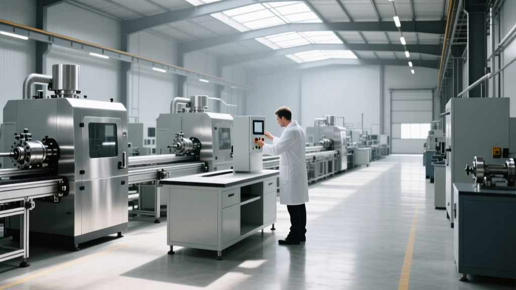
Batch equipment processes 50 to 150 wafers simultaneously in a single quartz tube. Systems like the Kokusai Electric DJ-series batch CVD furnaces or Tokyo Electron (TEL) Formula oxidation tubes remain the undisputed standard for mature nodes (28nm and above) and specific thick-film depositions where absolute angstrom-level uniformity is secondary to raw throughput.
Technical Specifications and CapEx
A standard vertical batch furnace operates at temperatures ranging from 400°C to 1,200°C. The primary economic advantage is the cost-per-wafer metric. A fully configured batch LPCVD (Low-Pressure Chemical Vapor Deposition) system typically costs between $2.2 million and $3.8 million. Because it processes 100 wafers per run, the amortized equipment cost per wafer is exceptionally low. Temperature uniformity across the batch is generally maintained within ±1.5°C, which is sufficient for gate oxides on mature planar transistors but inadequate for nanosheet GAAFET (Gate-All-Around) architectures.
Failure Modes and Edge Cases
Batch processing introduces specific physical failure modes. The most prevalent is quartz boat warping. At sustained 1,100°C operations, the silicon carbide or quartz wafer boats slowly deform, causing wafers to tilt by fractions of a degree. This tilt creates asymmetric gas flow, resulting in thickness gradients across the wafer surface. Additionally, batch tools suffer from 'boat mark' defects—localized particle contamination where the wafer contacts the boat slots. Edge exclusion (the unusable perimeter of the wafer) in batch systems is typically 2.5mm to 3.0mm due to gas flow turbulence at the tube walls.
Continuous-Flow Single-Wafer Systems: The Advanced Node Standard
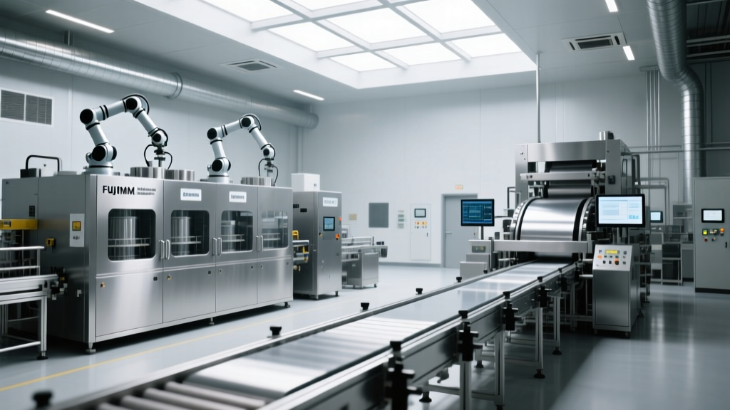
For sub-7nm logic and advanced DRAM, the industry has shifted to single-wafer platforms utilizing continuous-flow dynamics. Tools like the ASM International Eagle XP spatial ALD system represent the pinnacle of this architecture. Instead of pulsing gases and purging the chamber (which takes seconds per cycle), continuous spatial ALD separates precursor gases into distinct physical zones. The wafer rotates continuously under a gas-bearing susceptor, experiencing alternating chemical exposures in milliseconds.
Spatial ALD and Cluster Tool Dynamics
Continuous-flow systems achieve deposition rates up to 10 times faster than conventional temporal ALD while maintaining sub-angstrom thickness control. According to ASM International's ALD technology data, spatial ALD enables high-k dielectric deposition at throughputs that make single-wafer processing economically viable for high-volume manufacturing. The CapEx for these advanced continuous-flow cluster tools is steep, ranging from $6.5 million to $12 million per system, depending on the number of process modules and vacuum transfer chambers.
Yield Economics and Edge Exclusion
The financial justification for the high CapEx lies in yield recovery and edge exclusion. Continuous single-wafer systems utilize localized, closed-loop temperature control (often via multi-zone resistive heaters directly beneath the wafer), achieving temperature uniformity of ±0.5°C or better. Edge exclusion is reduced to <1.0mm. On a 300mm wafer, reclaiming that extra 1.5mm of perimeter space yields approximately 4% to 6% more functional die per wafer, which translates to millions of dollars in recovered revenue per month at advanced node pricing.
Architectural Comparison Matrix
| Parameter | Batch Multi-Wafer Furnace | Continuous-Flow Single-Wafer |
|---|---|---|
| Typical CapEx | $2.2M - $3.8M | $6.5M - $12.0M |
| Throughput (Wafers/Hour) | High (Batch amortized) | Moderate to High (Spatial ALD) |
| Temperature Uniformity | ±1.5°C (Zone controlled) | ±0.5°C (Multi-zone localized) |
| Edge Exclusion | 2.5mm - 3.0mm | < 1.0mm |
| Primary Node Application | > 22nm, Thick Oxides, 3D NAND | < 7nm Logic, GAAFET, High-k |
| Particle Defect Risk | High (Boat contact, gravity) | Low (Non-contact gas bearings) |
Case Study: 14nm FinFET to 3nm GAAFET Transition
Consider a Tier-1 foundry transitioning a production line from 14nm FinFET to 3nm GAAFET (Gate-All-Around) logic. At 14nm, the inner spacers and gate dielectrics were successfully deposited using batch LPCVD and standard cyclic single-wafer ALD. The yield loss from edge exclusion and minor thickness variations was absorbed by the large physical footprint of the FinFET transistors.
When engineering the 3nm GAAFET process, the foundry attempted to use upgraded batch furnaces for the nanosheet inner spacer deposition. The result was catastrophic for yield. The batch furnace's ±1.5°C thermal gradient caused a 4% variation in spacer thickness across the 300mm wafer. In a GAAFET architecture, where the gate wraps entirely around a silicon nanosheet measuring only 5nm in height, a 4% thickness variation alters the threshold voltage (Vt) beyond acceptable binning limits, resulting in a 12% drop in overall wafer yield.
The foundry replaced the batch equipment with continuous-flow spatial ALD cluster tools. According to broader industry CapEx analyses tracked by firms like McKinsey's semiconductor practice, advanced deposition tools now command a massive share of fab capital. Despite the $8.5 million price tag per spatial ALD tool, the continuous-flow system delivered ±0.2% thickness uniformity. The yield recovered to 88%, and the 1.5mm gain in edge exclusion yielded an additional 14 functional high-margin AI accelerator die per wafer, paying back the CapEx premium over the batch furnace in just 4.2 months of high-volume production.
Decision Framework: When to Deploy Which Architecture
Process engineers and fab planners should apply the following decision matrix when specifying wafer manufacturing equipment for new capacity:
- If the target node is > 22nm or the layer is > 500 Angstroms: Deploy batch multi-wafer furnaces. The sheer volume of precursor gas required for thick films makes continuous single-wafer processing economically unviable. Batch tools from Tokyo Electron or Kokusai remain the optimal choice for STI (Shallow Trench Isolation) fills and thick masking oxides.
- If the layer requires sub-5nm conformal coating over high aspect ratios (>50:1): Deploy continuous-flow spatial ALD. Batch furnaces cannot achieve the diffusion kinetics required to coat deep 3D NAND word-line trenches uniformly without unacceptable cycle times.
- If the fab is constrained by cleanroom footprint: Choose continuous single-wafer cluster tools. While batch furnaces process more wafers per run, the physical footprint of a 100-wafer vertical furnace, including the massive gas cabinets and abatement systems, often exceeds the footprint-to-throughput ratio of modern, highly integrated continuous-flow cluster tools.
Operational Maintenance and Consumable Realities
The total cost of ownership (TCO) extends far beyond the initial purchase price. Batch furnaces are heavily dependent on quartz and silicon carbide consumables. A standard 100-wafer quartz boat costs between $35,000 and $50,000 and must be replaced every 6 to 9 months due to thermal warping and surface pitting from aggressive fluorine-based cleaning chemistries. Furthermore, batch tubes require frequent wet cleans to remove particulate buildup, necessitating 12 to 18 hours of tool downtime per clean cycle.
Conversely, continuous-flow single-wafer systems eliminate quartz boats entirely, utilizing electrostatic chucks (ESCs) or gas-bearing susceptors. The primary consumable cost shifts to the precursor showerheads and localized heater arrays. Rebuilding a spatial ALD gas-injection showerhead typically costs around $12,000 to $18,000, and modern cluster tools are designed with modular swap-out cassettes that reduce maintenance downtime from 18 hours to under 4 hours. While the per-part cost for single-wafer components can be high, the reduction in catastrophic yield-excursion events (like a shattered quartz boat destroying 100 advanced wafers) heavily favors the continuous-flow architecture in high-margin production environments.