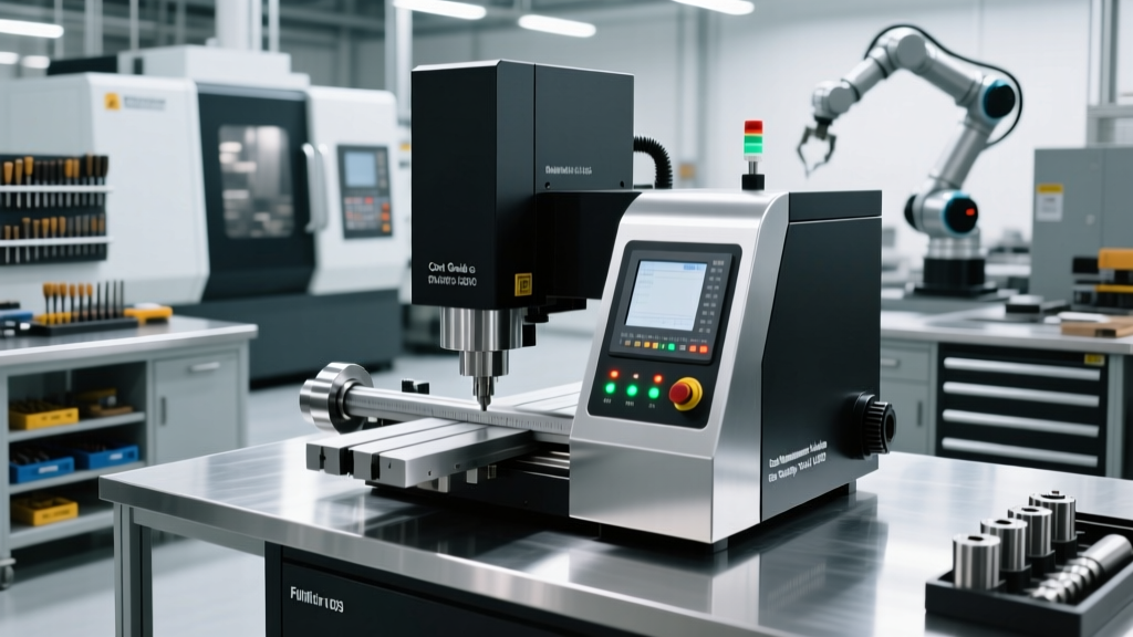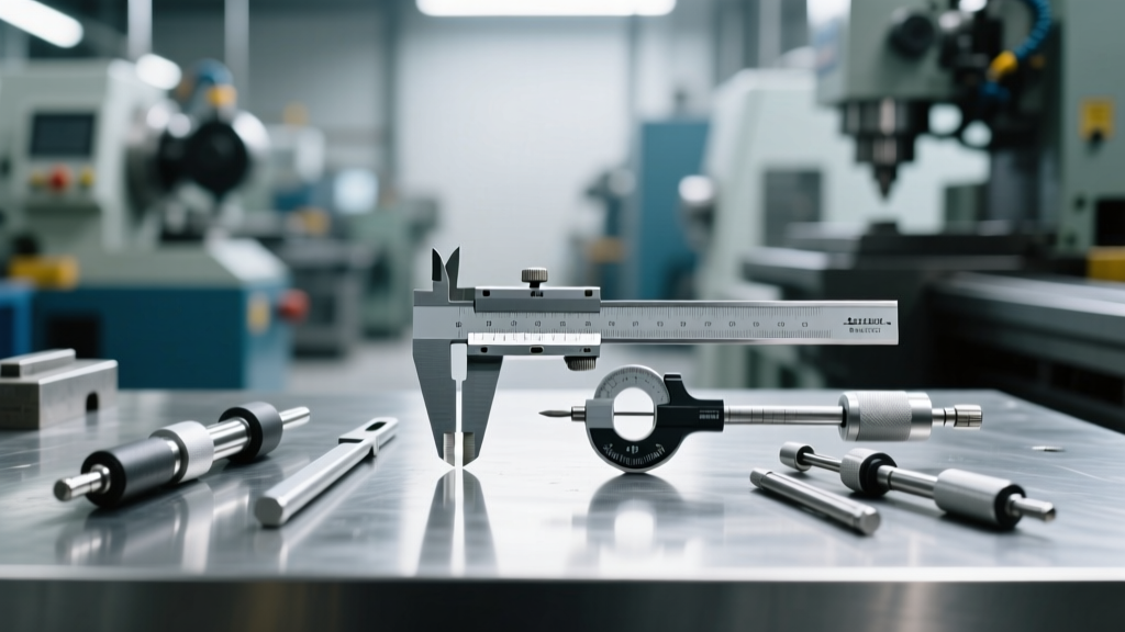
Precision Metrology Integration in Heavy Gauge Slitting Equipment
Explore how inline metrology and inspection systems integrate with heavy gauge slitting equipment to ensure precise width, thickness, and edge quality.
The Physics of Heavy Gauge Slitting and Metrology Challenges
Processing master coils into narrower mults requires immense mechanical force and exact geometric control. When operating heavy gauge slitting equipment—typically defined as lines processing carbon steel, stainless steel, or aluminum alloys from 3.0mm up to 16.0mm (0.118" to 0.630") thick—the shear forces involved generate significant thermal and mechanical deflection. Unlike light-gauge slitting, where material behaves almost like foil, heavy gauge metals exhibit a pronounced shear fracture zone consisting of rollover, burnish, fracture, and burr regions.
According to industry analysis by The Fabricator, the mechanics of the slitting process dictate that knife penetration must reach 15% to 30% of the material thickness before fracture occurs. In a 12mm thick high-strength low-alloy (HSLA) steel coil, this requires penetrating up to 3.6mm before the material breaks. This massive localized stress causes the strip to widen slightly (Poisson's effect) and generates intense friction heat. Inline metrology systems must account for these transient physical changes to maintain width tolerances of ±0.05mm and edge burr limits below 5% of the strip thickness.
Inline Measurement Technologies: A Technical Comparison
Modern heavy gauge slitting equipment relies on a multi-sensor approach to inspect the strip before, during, and after the slitter head. Below is a technical comparison of the primary metrology systems deployed on 2026-era slitting lines.
| Metrology Technology | Primary Application | Accuracy / Resolution | Sampling Rate | Heavy Gauge Limitations |
|---|---|---|---|---|
| Laser Triangulation (2D/3D) | Strip width, edge profile, camber | ±0.01mm / 1µm | 10 kHz - 50 kHz | Requires clean optical path; sensitive to heavy coolant mist. |
| X-Ray / Isotope Gauging | Continuous thickness profiling | ±0.1% of thickness | 100 Hz - 500 Hz | High capital cost; requires radiation safety shielding for >10mm steel. |
| Machine Vision (LED Backlit) | Edge burr detection, surface defects | 5µm spatial resolution | 60 - 120 fps | Struggles with reflective oiled surfaces without polarized filters. |
| Laser Profilometry | Knife clearance mapping, slit depth | ±0.005mm (Z-axis) | 2 kHz - 5 kHz | Must be retracted during threading to avoid mechanical damage. |
Laser Triangulation for Width and Edge Profiling
For width measurement, dual-head laser triangulation sensors are mounted on a precision C-frame or O-frame bridge immediately after the slitter head and scrap winders. As detailed in Keyence's laser profilometer specifications, modern 2D laser sensors project a line across the strip edge. By measuring the diffuse reflection angle, the system calculates the exact edge position. When processing 6mm thick steel at 100 meters per minute, a 10 kHz sampling rate yields a measurement point every 0.16mm, ensuring that even micro-camber deviations are captured and fed back to the line's automatic steering (EPC) system.
Knife Clearance and Overlap: The Critical Metrology Checkpoint
The most critical variable in heavy gauge slitting is the setup of the rotary knives. Incorrect clearance leads to excessive burr height, accelerated knife wear, and edge wave. Inline metrology systems now utilize automated tool-setting stations equipped with high-resolution laser displacement sensors to map the knife profile before the material is threaded.
- Side Clearance: Must be set to 5% to 8% of the material thickness. For 8.0mm steel, the target side clearance is 0.40mm to 0.64mm.
- Knife Overlap: Typically set to 10% to 15% of the material thickness (0.80mm to 1.20mm for 8.0mm steel).
- Arbor Deflection: Under a 500-ton separating force, the slitter arbor will deflect. Metrology software must apply a parabolic compensation curve to the knife spacing, shimming the outer knives slightly tighter to ensure uniform clearance across the entire 2000mm arbor face.
⚠️ Warning: Thermal Expansion Compensation
Heavy gauge slitting generates massive heat at the shear zone. Carbon steel has a linear thermal expansion coefficient of approximately 11.5 µm/m·°C. If a 1000mm wide strip experiences a 40°C temperature spike during a high-speed run, it will physically expand by 0.46mm. If the inline laser gauge does not integrate a pyrometer to read the strip temperature and apply real-time algorithmic compensation, the system will falsely register the strip as out-of-tolerance (too wide), causing the line to unnecessarily reject prime material.
Step-by-Step Calibration of Inline Laser Width Gauges
To maintain the ±0.05mm width tolerance required by ASTM A568 standards for steel sheet and coil, the inline measurement bridge must be calibrated weekly or after any mechanical impact. Follow this precise calibration protocol:
- Environmental Stabilization: Ensure the measurement enclosure temperature is within ±2°C of the factory baseline (typically 20°C). Allow the laser sensor electronics to warm up for a minimum of 45 minutes to prevent internal thermal drift.
- Optical Path Verification: Lockout/tagout the slitting line. Clean the sapphire protective windows on the laser sensor heads using isopropyl alcohol and lint-free wipes. Inspect for micro-scratches that could scatter the laser beam.
- Master Gauge Block Insertion: Insert NIST-traceable tungsten carbide master gauge blocks across the measurement span. Use three distinct widths representing the operational range: e.g., 200.000mm, 800.000mm, and 1500.000mm.
- 5-Point Linearity Check: Traverse the master block across the sensor's field of view in 50mm increments. Record the sensor output at each point. The maximum deviation from the master block dimension must not exceed ±0.008mm.
- Dynamic Velocity Simulation: Run a calibration strip through the line at the maximum operational speed (e.g., 120 m/min). Compare the dynamic inline measurement against a static post-process CMM (Coordinate Measuring Machine) reading. Adjust the encoder pulse multiplier in the PLC until the dynamic and static readings match within 0.02mm.
Edge Burr Inspection via Machine Vision
Burr formation is the primary indicator of knife degradation in heavy gauge slitting. A burr exceeding 5% of the strip thickness (e.g., >0.40mm on an 8.0mm coil) can cause severe issues in downstream stamping and welding operations. Modern inspection systems utilize high-intensity, polarized LED line lights positioned at a 15-degree angle to the strip edge, paired with 4K line-scan cameras.
The vision system captures the shadow profile of the edge. Advanced edge-detection algorithms calculate the burr height in real-time. If the burr height trends upward by 0.05mm over a 500-meter run length, the system triggers a predictive maintenance alert, indicating that the slitter knives require indexing or grinding before the burr breaches the absolute rejection limit. This predictive metrology shifts quality control from reactive scrap sorting to proactive process management, ensuring that heavy gauge slitting equipment operates at peak geometric precision throughout the entire coil.
Expert Insight: 'In heavy gauge slitting, metrology is not just about measuring the final product; it is about measuring the machine's behavior under load. If you are not measuring arbor deflection and thermal strip expansion simultaneously, your width data is fundamentally flawed.' — Senior Process Engineer, Coil Processing Division.