Maintenance Protocols When Machining CNC Aerospace Alloys
Discover exact maintenance schedules and service protocols for machining CNC aerospace components. Prevent tolerance drift in 5-axis titanium milling.
When machining CNC aerospace components from Ti-6Al-4V or Inconel 718, standard job-shop maintenance intervals are a recipe for catastrophic tolerance drift. Aerospace structural bulkheads and turbine blisks demand volumetric accuracies within ±5 microns. Achieving this on a 5-axis platform like the DMG MORI DMU 50 or Mazak VARIAXIS i-800 requires a maintenance architecture built around thermal stability, chip evacuation, and axis geometry verification. Under AS9100 Rev D quality management standards, machine tool maintenance is no longer just about preventing breakdowns; it is a critical, documented variable in the part certification process.
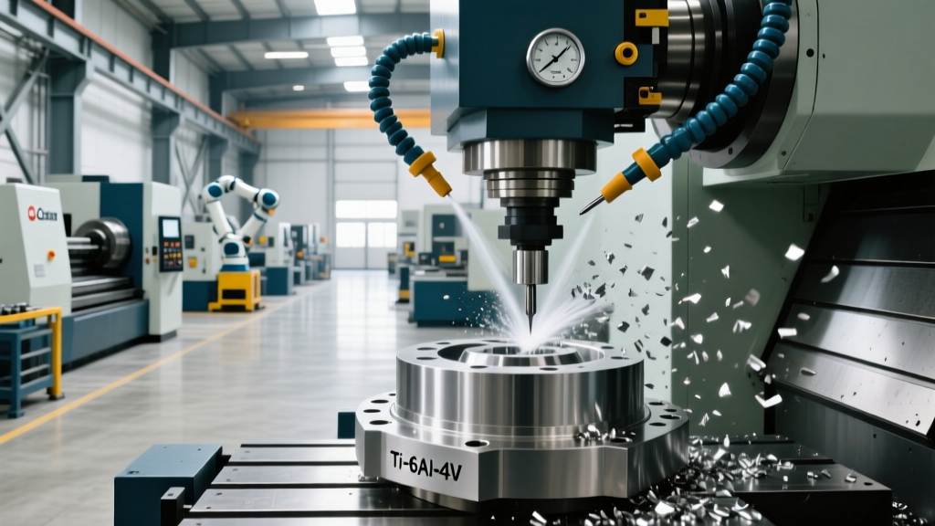
⚠️ WARNING: The Titanium Chip HazardTitanium generates stringy, work-hardened chips that easily weld to machine tapers and way covers. If these chips infiltrate the axis guideways or the automatic tool changer (ATC) arm, they cause immediate micro-pitting on linear scales and catastrophic taper run-out. Standard chip conveyors are insufficient; high-pressure coolant flushing and manual way-cover inspections are mandatory every 4 hours during heavy roughing cycles.
Fluid Management and Filtration for Exotic Alloys
Machining aerospace superalloys generates immense localized heat. Unlike aluminum machining, where coolant primarily acts as a lubricant and chip-flusher, titanium and Inconel require coolant to aggressively suppress thermal expansion in both the cutting tool and the workpiece. Standard 5% coolant concentrations will fail under these loads, leading to rapid tool wear and workpiece rejection.
According to Sandvik Coromant's titanium milling guidelines, maintaining precise coolant chemistry is vital to prevent chemical reactions at the cutting edge. Tramp oil from way lubrication skews refractometer readings, leading operators to over-concentrate the mixture, which subsequently degrades the coolant's ability to penetrate the cutting zone.
| Maintenance Task | Frequency | Aerospace Specification / Target |
|---|---|---|
| Coolant Concentration Check | Daily (Start of Shift) | 8.0% - 10.0% (Corrected for tramp oil) |
| Coolant pH Level Testing | Twice Weekly | 8.8 - 9.2 (Prevents bacterial growth & corrosion) |
| Tramp Oil Skimmer Operation | Continuous / Daily Check | Less than 1.5% tramp oil volume in sump |
| Coolant Filter Media Replacement | Weekly / Based on PSI | 20-micron nominal filtration for high-pressure pumps |
| Way Lube Level & Flow Check | Daily | Mobil Vactra No. 2 or OEM equivalent; verify flow at all axes |
Spindle Thermal Growth and Run-Out Calibration
The most critical variable in 5-axis aerospace machining is spindle thermal growth. A 15,000 RPM HSK-A63 spindle can experience 15 to 25 microns of Z-axis thermal expansion during the first 45 minutes of operation. If an operator begins machining a tight-tolerance titanium fitting on a cold spindle, the first batch of parts will be out of spec by the time the spindle reaches thermal equilibrium.
Mandatory Thermal Conditioning Protocols
- Automated Warm-Up Macros: Program a 15-minute spindle warm-up cycle that ramps RPM from 2,000 to 12,000 in 2,000 RPM increments, while simultaneously sweeping the X, Y, and Z axes through 50% of their total travel. This distributes bearing grease and stabilizes the spindle housing temperature.
- Ceramic Bearing Greasing: For grease-packed ceramic hybrid bearings (common in high-speed aerospace spindles), manual greasing intervals must be strictly followed. Over-greasing causes excessive churning friction, leading to thermal runaway and bearing seizure. Use exact OEM-specified volumetric grease pumps, typically dispensing 0.5cc to 1.0cc per interval.
- Run-Out Verification: Use a calibrated test arbor and a 0.0001" dial indicator weekly. HSK-A63 tapers must maintain less than 3 microns of radial run-out at the gage line. If run-out exceeds this, the spindle taper must be professionally reground or the drawbar mechanism inspected for Belleville spring fatigue.
Unplanned spindle replacement on a premium 5-axis machine costs between $28,000 and $45,000, not including the 4-to-8-week lead time for factory repair. Adhering to thermal conditioning and precise greasing protocols extends spindle life from an average of 8,000 hours to over 15,000 hours.
ATC and Tool Holder Taper Maintenance
When roughing Inconel 718, radial cutting forces frequently exceed 2,500 N. These extreme forces test the limits of the tool retention system. The pull-stud (retention knob) on the tool holder is subjected to immense cyclic tensile stress. If a pull-stud fractures inside the spindle during a cut, the tool drops, resulting in a scrapped $10,000 aerospace forging and severe spindle damage.
💡 Expert Insight: Pull-Stud Stretch LimitsDo not rely solely on visual inspections for pull-studs. Use a micrometer to measure the length of 4340 alloy steel pull-studs every 6 months. If the stud has stretched beyond 0.0005" (0.0127mm) from its original factory specification, the metallurgical integrity is compromised. Discard and replace immediately. Always torque pull-studs to the exact manufacturer specification (typically 40-50 ft-lbs for HSK63) using a calibrated torque wrench, never an impact driver.
Furthermore, the ATC arm alignment must be verified quarterly. A misaligned ATC arm causes the tool holder to strike the spindle taper at an angle, micro-chipping the ceramic coating on the spindle nose. Use a specialized taper cleaning tool (such as those from NTN or Heimatec) wrapped in a lint-free cloth and isopropyl alcohol to clean the spindle taper every 4 hours during titanium machining operations to prevent chip welding.
Axis Geometry and Volumetric Accuracy Verification
Aerospace components often require simultaneous 5-axis contouring. If the rotary axes (B and C, or A and C) are not perfectly orthogonal to the linear axes, the machine will introduce cosine errors that compound across the part geometry. Relying solely on the machine's internal encoders is insufficient, as mechanical wear, thermal expansion, and minor collisions alter the physical geometry of the machine over time.
The NIST Advanced Manufacturing portal emphasizes the necessity of regular metrology integration directly on the shop floor to maintain precision in complex manufacturing environments. To achieve this, implement the following metrology schedule:
- Monthly Ballbar Testing: Use a wireless ballbar system (e.g., Renishaw QC20-W) to perform circular interpolation tests. Run the test at a feed rate of 1000 mm/min with a 150mm radius. This will immediately identify servo mismatch, backlash, and stick-slip errors in the linear axes. Squareness errors between axes must be kept below 5 microns per 300mm.
- Bi-Annual Volumetric Compensation: Utilize a laser tracker or a specialized on-machine probing routine (like Haas NGC probing or DMG MORI's 3D quickSET) to map the kinematic chain of the 5-axis machine. This updates the machine's internal pivot point parameters (Tool Center Point Control - TCPC), ensuring the spindle tip remains perfectly aligned with the programmed coordinate system regardless of rotary table position.
- Post-Collision Recalibration: Any crash exceeding 500 N of force requires an immediate halt to production and a full volumetric recalibration. Micro-fractures in the cast iron or shifted linear guideways will invalidate all previous compensation maps.
Electrical Cabinet and Control Cooling
Aerospace machining cycles often run unattended for 12 to 24 hours. The control cabinet houses the drives, PLC, and processing unit, generating significant heat. If the cabinet air conditioner fails or the filters clog with ambient shop dust, the internal temperature rises. Modern CNC controls will throttle processing speed or trigger thermal alarms to prevent board damage, resulting in dwell marks on the aerospace part surface finish.
- Filter Replacement: Replace cabinet AC intake filters every 30 days. Do not use compressed air to blow them out, as this forces conductive metallic dust deeper into the filter media and eventually into the cabinet.
- Seal Inspection: Check the door gaskets quarterly. A compromised seal allows humid, oil-laden shop air to enter the cabinet, leading to corrosion on the drive terminals and intermittent communication faults between the CNC brain and the axis amplifiers.
For comprehensive OEM-specific intervals and torque specifications, always cross-reference your maintenance actions with the official Haas Automation service documentation or your respective machine builder's technical portal. Documenting every fluid change, ballbar test, and pull-stud inspection in a centralized digital log is not just best practice; it is a mandatory requirement for passing rigorous aerospace prime contractor audits.