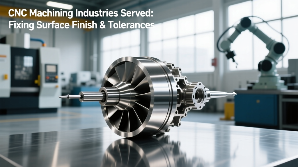
CNC Machining Industries Served: Fixing Surface Finish & Tolerances
Diagnose and repair CNC surface finish and tolerance failures across aerospace, medical, and automotive sectors with industry-specific troubleshooting matrices.
When auditing the specific CNC machining industries served by a contract manufacturing facility, the diagnostic approach to a surface finish or tolerance failure must shift to match the sector's governing standards. A surface roughness deviation of Ra 1.6 µm (63 µin) might trigger an automatic scrap protocol in orthopedic implant manufacturing (ISO 13485), while passing as acceptable in heavy agricultural equipment housings. Similarly, geometric dimensioning and tolerancing (GD&T) failures governed by ASME Y14.5 require entirely different machine calibration interventions depending on whether the workpiece is 7075-T6 aluminum or Ti-6Al-4V titanium.
Diagnostic Premise: Surface texture (ISO 21920) and dimensional drift are rarely isolated tooling issues. They are systemic machine-tool-workpiece interactions. Troubleshooting must begin by identifying the industry-specific failure mode before adjusting feeds, speeds, or spindle offsets.The Diagnostic Matrix: Matching Symptoms to Industry Standards
The root cause of a tolerance or finish failure is heavily dictated by the material and the production volume typical of the target industry. Use this matrix to isolate the primary mechanical or thermal fault on the shop floor.
| Symptom / Defect | Primary Industry Affected | Governing Standard | Root Cause & Machine Fault | Targeted Repair / Adjustment |
|---|---|---|---|---|
| Micro-chatter & Ra > 0.8 µm | Medical (Implants) | ISO 13485 / AS9100 | Toolholder runout > 0.0002"; harmonic resonance in finishing endmills. | Replace ER collets with hydraulic or shrink-fit toolholders; apply variable helix geometry tools. |
| Thermal Drift (Z-axis shift) | Aerospace (Structural) | AS9100 / NADCAP | Spindle bearing preload loss; inadequate thermal compensation in the CNC controller. | Re-tension spindle drawbar; enable real-time thermal displacement compensation via spindle nose sensors. |
| Built-Up Edge (BUE) & Tearing | Automotive (Powertrain) | IATF 16949 | Insufficient coolant pressure at the shear zone; incorrect insert edge prep (lack of honing). | Upgrade to 1000+ PSI high-pressure coolant pumps; switch to PVD-coated inserts with 15µm edge hone. |
| Stick-Slip & Way Friction Marks | Heavy Machinery / Energy | ISO 9001 / API | Clogged metering units in the automatic way lube system; degraded way oil viscosity. | Flush way lube lines; replace restrictors; switch to ISO VG 68 way oil with tackifier additives. |
Micro-Tolerance Diagnostics: Aerospace & Medical Sectors
Facilities focused on the high-precision CNC machining industries served—specifically aerospace turbine components and medical orthopedics—operate at the extreme limits of machine rigidity. Tolerances here frequently demand ±0.0002" (5 µm) positional accuracy and surface finishes of Ra 0.4 µm or better.
Spindle Runout and Toolholder Deflection
In medical titanium machining, a surface finish failure manifesting as microscopic chatter marks is almost always a toolholding issue, not a spindle bearing failure. Standard ER32 collet chucks exhibit radial runout of 0.0004" to 0.0008" at 3x diameter extension. This runout causes uneven flute engagement, destroying the Ra 8 µin finish required for bone-ingrowth surfaces.
- The Fix: Mandate hydraulic chucks or thermal shrink-fit toolholders for all finishing operations. Shrink-fit holders guarantee radial runout of less than 0.0001" (2.5 µm) at 3x diameter.
- Verification: Use a dial indicator with 0.0001" resolution on the tool shank. If runout exceeds 0.00015", inspect the spindle taper for micro-fretting corrosion using a blueing compound test.
Thermal Growth in 5-Axis Aerospace Milling
When roughing Inconel 718, the spindle generates immense internal heat. If the Z-axis drops by 0.0015" over a 4-hour cycle, the part will fail AS9100 first-article inspection. This is thermal growth, not axis backlash.
Expert Insight: Do not attempt to fix thermal Z-drift by tightening axis gibs. Instead, implement a spindle warm-up macro that runs at 8,000 RPM for 15 minutes before the first cut, and ensure the machine's casting is shielded from direct HVAC drafts, which cause asymmetric thermal bowing of the column.
Macro-Finish Diagnostics: Automotive & High-Volume Production
Shops catering to the automotive CNC machining industries served prioritize cycle time and tool life over micro-finishes. A typical transmission housing requires Ra 3.2 µm (125 µin) and tolerances of ±0.001". Failures here are usually tied to high-volume wear mechanisms and way lubrication.
Chatter and Insert Flank Wear
In high-speed aluminum milling (e.g., Al 6061-T6 at 15,000 SFM), poor surface finish often presents as macroscopic chatter or visible feed marks. This is frequently caused by spindle imbalance at high RPMs or improper insert edge preparation.
- The Fix: Check the tool assembly balance grade. For RPMs above 10,000, toolholders must be balanced to ISO 1940-1 G2.5 standards. Use balanced toolholders with adjustable eccentric rings.
- Edge Prep: If machining cast iron or forged steel, ensure carbide inserts feature a T-land or chamfered edge prep. A sharp edge will micro-chip within 50 parts, causing immediate surface finish degradation.
Way Lubrication and Stick-Slip Errors
If a CNC lathe or horizontal mill produces a wavy surface finish during heavy facing operations, the saddle may be experiencing stick-slip friction. This occurs when the static friction coefficient of the way surfaces exceeds the dynamic friction, causing the axis to jump in micro-increments.
- Inspect the automatic way lube pump reservoir. Ensure it is filled with dedicated way oil (e.g., Mobil Vactra Oil No. 2), not standard hydraulic fluid.
- Manually trigger the lube pump and verify that oil weeps from all four corners of the saddle and cross-slide.
- Clear clogged metering units (often located near the axis wipers) using compressed air and a solvent flush.
Step-by-Step Axis Calibration for Tolerance Failures
When GD&T callouts like true position or circularity fail consistently across multiple setups, the machine's geometric volumetric accuracy is compromised. Follow this diagnostic flow using a Renishaw QC20-W ballbar system or equivalent laser interferometer.
Warning: Never adjust machine geometry parameters (like pitch error compensation) without first verifying the ballscrew thrust bearings. A loose thrust bearing will mimic backlash in the ballbar test, leading to incorrect software compensation and catastrophic crashes.- Run a 150mm Radius XY Circular Test: Mount the ballbar and run a clockwise and counter-clockwise test at 1000 mm/min.
- Analyze the Polar Graph: Look for an 'oval' shape tilted at 45 degrees. This indicates axis squareness error (the X and Y axes are not perfectly perpendicular).
- Correct Squareness: Loosen the saddle way cover and adjust the master square alignment using a precision granite square and a 0.00005" test indicator.
- Check for Backlash: If the polar graph shows a 'spike' or discontinuity at the axis reversal points, measure the physical backlash. If physical backlash exceeds 0.0003", replace the ballscrew thrust bearings before altering the CNC controller's backlash compensation parameters.
Quick Reference: Surface Finish & Tolerance Standards by Sector
Maintenance technicians and process engineers must align their troubleshooting targets with the specific expectations of the CNC machining industries served. Use this baseline to determine if a machine is truly out of spec, or if the process expectations are misaligned with the machine's physical capabilities.
| Industry Sector | Typical Tolerance Band | Target Surface Finish (Ra) | Primary Calibration Tool |
|---|---|---|---|
| Medical (Implants) | ± 0.0002" (5 µm) | 0.2 - 0.8 µm | Laser Interferometer |
| Aerospace (Turbine) | ± 0.0005" (12 µm) | 0.8 - 1.6 µm | Ballbar & Spindle Analyzer |
| Automotive (Engine) | ± 0.0010" (25 µm) | 1.6 - 3.2 µm | Ballbar & Dial Indicators |
| Heavy Equipment | ± 0.0050" (125 µm) | 3.2 - 6.3 µm | Precision Levels & Straightedges |
Resolving surface finish and tolerance deviations requires moving beyond simple toolpath adjustments. By mapping the specific failure mode to the governing industry standard and executing targeted mechanical repairs—whether that means upgrading to hydraulic toolholding for medical micro-finishes or flushing way lube restrictors for heavy machinery facing—shops can restore machine accuracy and eliminate costly scrap rates.
Authoritative References
- ISO 21920-1:2021 - Surface texture: Profile method (International Organization for Standardization)
- ASME Y14.5 - Dimensioning and Tolerancing Standard (American Society of Mechanical Engineers)
- Metal Cutting Milling Knowledge & Troubleshooting (Sandvik Coromant)