CNC Machining Expert Guide to Secondary Operations
Master CNC post-processing and secondary operations. Learn expert deburring, anodizing prep, and heat treatment fixturing to eliminate scrap.
The Handoff: Protecting the Substrate Before Secondary Ops
The transition from the CNC machine bed to post-processing is where profit margins are most frequently destroyed. A true CNC machining expert understands that the cutting cycle is only half the battle; secondary operations dictate the final geometric accuracy, surface integrity, and cosmetic quality of the part. Mishandling parts immediately after unclamping introduces variables that no amount of downstream finishing can fix.
Operator training must begin with substrate protection. Bare skin contact deposits chlorides and sebaceous oils onto freshly machined surfaces. On austenitic stainless steels (like 303 and 304) and aluminum alloys, these contaminants initiate localized galvanic corrosion within hours, manifesting as micro-pitting that will be permanently locked in during anodizing or passivation.
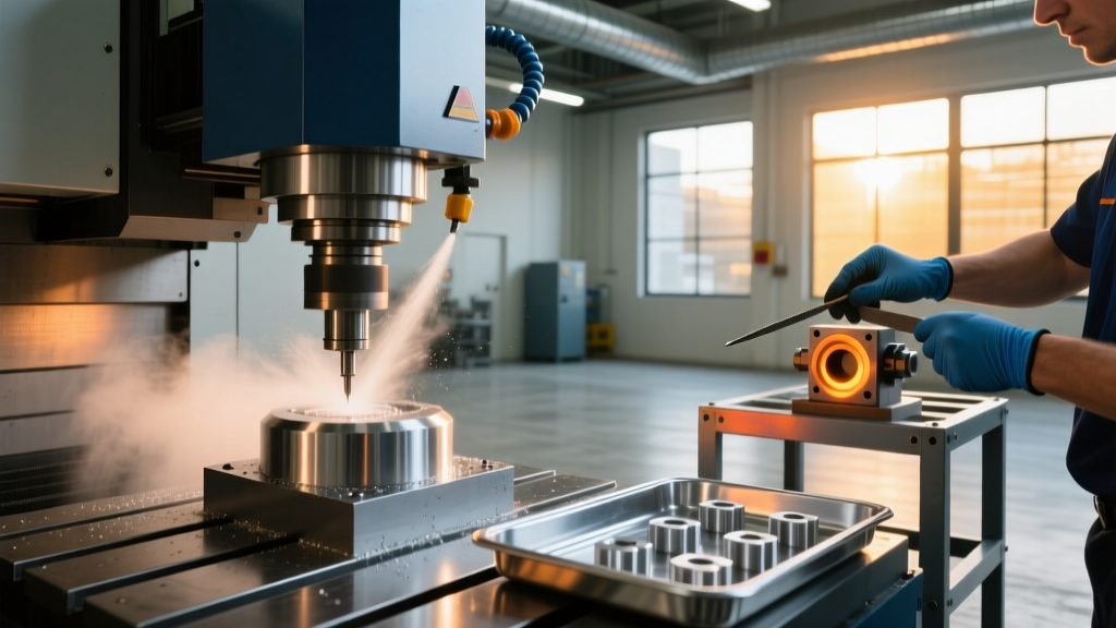
OPERATOR DIRECTIVE: Mandate the use of powder-free nitrile gloves (minimum 4-mil thickness) for all part removal and transfer. Cotton gloves absorb ambient humidity and transfer salts; latex leaves sulfur residues that interfere with silver or tin plating. Parts must be placed on cross-linked polyethylene (XLPE) foam, never directly on steel workbenches or bare MDF.Deburring and Edge Breaking: The First Line of Defense
Edge conditioning is not merely cosmetic; it dictates fatigue life and assembly fitment. Sharp internal corners act as stress concentrators, reducing the fatigue limit of cyclically loaded components by up to 40%. Operators must be trained to select the correct deburring methodology based on the material's ductility and the part's geometric complexity.
For manual edge breaking, operators should abandon high-speed steel (HSS) countersinks, which often chatter and create secondary burrs on gummy materials like 6061-T6 aluminum or pure copper. Instead, utilize carbide micro-grain deburring blades with a TiAlN coating, or 3M Scotch-Brite radial bristle discs (grade 80 for heavy stock removal, grade 400 for final edge radiusing). For internal intersecting holes, thermal energy machining (TEM) or abrasive flow machining (AFM) are the only reliable methods to guarantee a burr-free intersection without manual intervention.
Decision Matrix: Secondary Deburring Methodologies
| Method | Best Application | Cycle Time / Part | Estimated Cost | Edge Break Quality |
|---|---|---|---|---|
| Manual (Hand Tools) | Low volume, large aerospace structures | 5 - 15 mins | $12 - $25 labor | Variable (operator dependent) |
| Vibratory Tumbling | High volume, robust geometries, steel/brass | 45 - 120 mins | $0.50 - $2.00 | Uniform radius, can damage fine threads |
| Thermal Energy (TEM) | Complex hydraulics, internal cross-holes | 30 - 90 seconds | $3.00 - $8.00 | Perfect internal edge radiusing |
| Cryogenic Deflashing | Polymers, elastomers, soft aluminum burrs | 15 - 30 mins | $1.50 - $4.00 | Excellent for non-metallic flash |
Surface Preparation for Anodizing and Plating
Achieving a flawless Type II or Type III (Hardcoat) anodized finish requires precise surface roughness control during the initial CNC milling or turning operation. According to the guidelines established in ISO 21920-1:2021 for surface texture, the target arithmetic mean deviation (Ra) for cosmetic anodizing should be between 0.4 µm and 0.8 µm (Ra 16 to 32 µin).
If the as-machined surface is too smooth (below 0.2 µm), the anodizing etch tank will struggle to bite into the substrate, leading to poor adhesion and coating flaking. If the surface is too rough (above 1.6 µm), the anodic layer will replicate the tool marks, resulting in a dull, mottled appearance regardless of the dye used.
Expert Insight on Alloy Variations: Operators must adjust prep protocols based on the specific aluminum series. 7075-T6 contains high copper levels. If subjected to the same sodium hydroxide etch times as 6061-T6, the copper will precipitate out as a heavy black smut. A CNC machining expert will specify a 15-20% shorter etch cycle and a dedicated desmutting dip in nitric acid for 7000-series alloys prior to the anodizing tank.
Masking Protocols for Critical Tolerances
Anodic coatings grow outward and inward from the base metal surface. The standard rule of thumb is the 50/50 rule: 50% of the coating thickness penetrates the substrate, and 50% builds up externally. For a standard 0.0005-inch Type II coat, the part will grow by 0.00025 inches per side.
When holding tight bore tolerances (e.g., +0.0000" / -0.0005"), operators must apply masking. Liquid maskants (like Plasti Dip) are insufficient for high-precision bores due to capillary action bleeding. Instead, train operators to use pull-through silicone masking plugs or custom-machined PTFE (Teflon) mandrels. PTFE is chemically inert to the sulfuric and chromic acid baths and provides a zero-bleed seal.
Heat Treatment Distortion Mitigation
Secondary heat treatment operations, such as quenching and tempering, introduce massive thermal stresses that warp CNC-machined geometries. Distortion is particularly severe in asymmetric parts or thin-walled housings machined from 4140 or 4340 alloy steels.
To mitigate this, machining operations must be sequenced correctly. Rough machining should be performed on pre-hardened stock (28-32 HRC). Before sending the part to the heat treater for final hardening (50-55 HRC), a stress-relieving bake is mandatory. Operators and programmers must schedule a stress relief cycle at 1100°F (593°C), holding for one hour per inch of maximum cross-sectional thickness, followed by a slow furnace cool. This relaxes the residual stresses induced by the roughing passes.
Furthermore, when designing fixtures for the heat treat quench, parts must be suspended vertically to ensure uniform oil or polymer quenchant flow. Horizontal stacking creates vapor blankets (the Leidenfrost effect), resulting in uneven cooling rates, soft spots, and severe bowing. Reference the quenching protocols outlined by ASTM standards for thermal processing to ensure proper rack spacing.
Troubleshooting Post-Processing Defects
Even with rigorous protocols, secondary operations can yield defective parts. Operators must be trained to diagnose the root cause rather than simply scrapping the component. Use this diagnostic framework to identify and correct common post-machining failures.
Symptom 1: Micro-Pitting or 'Starburst' Defects After Hardcoat Anodizing
- Cause: Chloride contamination trapped in blind holes or porous areas from previous tapping or coolant operations. Chlorides react violently in the sulfuric anodizing bath.
- Fix: Implement an ultrasonic cleaning stage (40 kHz frequency) in a 5% alkaline solution for 10 minutes prior to the anodizing rack-up. Never use halogenated tapping fluids on parts destined for anodizing.
Symptom 2: Dimensional Growth Exceeds Tolerance After Plating
- Cause: Incorrect assumption of plating build-up. Electroless nickel (EN) plates uniformly, but electrolytic zinc or chrome builds up heavily on sharp external corners due to high current density (the dog-bone effect).
- Fix: Programmers must add 0.001" to 0.002" edge breaks on all external corners during the CNC toolpath generation to distribute the electrical current evenly during the plating bath.
Symptom 3: Part Warpage Post-Machining and Pre-Assembly
- Cause: Removing too much material from one side of a billet without flipping and stress-relieving, leaving unbalanced internal residual stresses.
- Fix: Adopt a symmetric machining strategy. Remove 50% of the total stock from Side A, flip, and remove 50% from Side B. Allow the part to rest for 24 hours at room temperature before executing the final finishing passes. Consult advanced fixturing strategies via the Sandvik Coromant Knowledge Hub for thin-wall milling techniques.
Final Quality Control Checkpoints
Secondary operations alter the physical dimensions and surface properties of a part, meaning the final CMM (Coordinate Measuring Machine) inspection must occur after all post-processing is complete. Operators must recalibrate probing routines to account for the altered surface friction. Anodized and plated surfaces require larger ruby or silicon nitride probe styluses (minimum 3mm diameter) to prevent the probe tip from skidding or scratching the hardened coating, which introduces false deviation readings in the GD&T report.