Carbon Fiber CNC Machining: Safety & Tolerances for Enclosures
Master carbon fiber CNC machining for electronics enclosures. Explore OSHA dust safety, tight-tolerance EMI shielding, and UL 94 compliance frameworks.
Occupational Safety: Managing Conductive CFRP Particulates
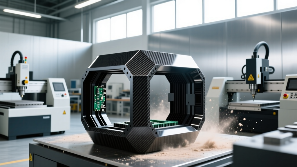
Machining CFRP generates microscopic carbon fibers (typically 5–10 microns in diameter) and epoxy dust. Because these particulates are highly electrically conductive, standard machine shop environments face a severe secondary hazard: if carbon dust escapes the CNC enclosure and settles on nearby PCB assembly lines or testing equipment, it causes catastrophic micro-shorts and component failure.
OSHA Compliance Alert: Under OSHA Standard 1910.1000 (Table Z-1), the Permissible Exposure Limit (PEL) for nuisance dust and particulates not otherwise classified is 15 mg/m³ (total dust) and 5 mg/m³ (respirable fraction). Carbon fiber dust requires dedicated HEPA filtration with anti-static grounding. Standard shop vacuums will ignite due to static discharge buildup from the conductive CF dust.To protect both the operator and the electronics manufacturing ecosystem, 5-axis CNC cells dedicated to carbon fiber must utilize negative-pressure downdraft tables paired with statically grounded, explosion-proof HEPA extraction units. Operators must wear N95 or P100 respirators, as the rigid, splintered nature of carbon fibers can cause severe respiratory irritation and mechanical damage to lung tissue.
EMI/RFI Shielding and MIL-STD-461 Compliance
Carbon fiber is inherently conductive, but the epoxy resin matrix binding the fibers is an insulator. To create a Faraday cage effect for sensitive avionics or 5G/6G telecommunications hardware, the CNC-machined mating surfaces must expose the raw carbon weave to make direct electrical contact with conductive gaskets (such as silver-aluminum filled silicone or beryllium copper finger stock).
If the CNC router bit is dull or improperly configured, it will 'smear' the epoxy resin over the carbon fibers at the cut edge. This resin-rich layer acts as a dielectric barrier, causing electromagnetic interference (EMI) leakage at high frequencies. Achieving compliance with MIL-STD-461 for radiated emissions requires precise control over the machining parameters to ensure fiber exposure.
| CNC Surface Finish (Ra) | Resin Smearing Level | Conductive Gasket Compression | EMI Shielding Effectiveness |
|---|---|---|---|
| 125 µin (3.2 µm) | High (Dull Tooling) | Poor Electrical Contact | < 20 dB (Fails MIL-STD-461) |
| 63 µin (1.6 µm) | Moderate | Intermittent Contact | 40 - 50 dB (Marginal) |
| 32 µin (0.8 µm) | None (CVD Diamond Tooling) | Optimal Fiber-to-Gasket Contact | > 80 dB (Compliant) |
Tooling Strategies to Prevent Resin Smearing
Standard uncoated carbide end mills degrade within 40 linear feet of cutting CFRP, leading to edge delamination and resin smearing. For tight-tolerance enclosure perimeters, machine shops must invest in Chemical Vapor Deposition (CVD) diamond-coated compression spiral bits. While these tools cost 300% more than standard carbide ($120–$180 per tool vs. $35), they extend tool life to over 250 linear feet and maintain the critical 32 µin surface finish required for EMI sealing.
- Spindle Speed: 18,000 – 24,000 RPM (High speed prevents epoxy tearing).
- Feed Rate: 100 – 150 IPM (Maintains chip load to evacuate heat).
- Coolant: NEVER use flood coolant. Liquid contaminates the porous CFRP edge and destroys the adhesive bonding of secondary EMI gaskets. Use cryogenic air cooling or specialized minimum quantity lubrication (MQL) with evaporative synthetic fluids.
Environmental Sealing: IP67 and AS568 O-Ring Tolerances
Outdoor and aerospace electronics enclosures frequently require IP67 or IP68 environmental sealing. This necessitates machining precise O-ring grooves directly into the carbon fiber flange. CFRP is prone to micro-tearout at the edges of deep, narrow grooves, which compromises the sealing surface and leads to moisture ingress.
When programming toolpaths for O-ring grooves, engineers must reference the AS568 Aerospace Standard for O-ring gland dimensions. Because carbon fiber cannot be compressed or deformed like aluminum to compensate for a poor seal, the CNC machined groove width and depth must be held to extremely tight tolerances.
Machining Tip: For an AS568-225 O-ring (1/8" cross-section), the standard groove width is 0.177". In CFRP, machine the groove width to 0.179" (+0.002" / -0.000") to account for microscopic fiber tearout, ensuring the O-ring compresses laterally without binding against jagged carbon edges.Flammability Standards: Achieving UL 94 V-0
Standard aerospace epoxies (like typical 350°F cure toughened systems) often fail the UL 94 V-0 flammability test, which is mandatory for commercial electronics enclosures to prevent fire propagation. If your application requires UL 94 V-0 compliance, you cannot use standard dry carbon fiber and wet layup resins.
You must source specialized fire-retardant prepregs. Materials such as HexPly® M77 or phenolic-matrix carbon fiber sheets are engineered to self-extinguish. However, phenolic matrices are significantly more brittle and abrasive than epoxy. When CNC machining phenolic CFRP, reduce the depth of cut (DOC) by 30% and increase the spindle RPM by 15% to prevent catastrophic edge chipping at the enclosure corners.
Quality Assurance: Non-Contact CMM Inspection
Verifying the ±0.002-inch flatness of a carbon fiber enclosure mating surface using a standard touch-probe Coordinate Measuring Machine (CMM) is highly discouraged. The ruby or silicon nitride stylus tip can drag across the CFRP surface, catching on exposed fibers and causing micro-fraying that ruins the EMI sealing surface.
Instead, utilize non-contact laser line scanning or white-light structured scanning for quality assurance. These optical methods map the surface topography at the micron level without applying mechanical force. When programming the CMM, set the scanner to capture data at a minimum resolution of 50 microns per point to accurately detect the resin-rich vs. fiber-exposed zones along the machined perimeter, ensuring the enclosure will pass both environmental and electromagnetic compliance testing on the first assembly attempt.