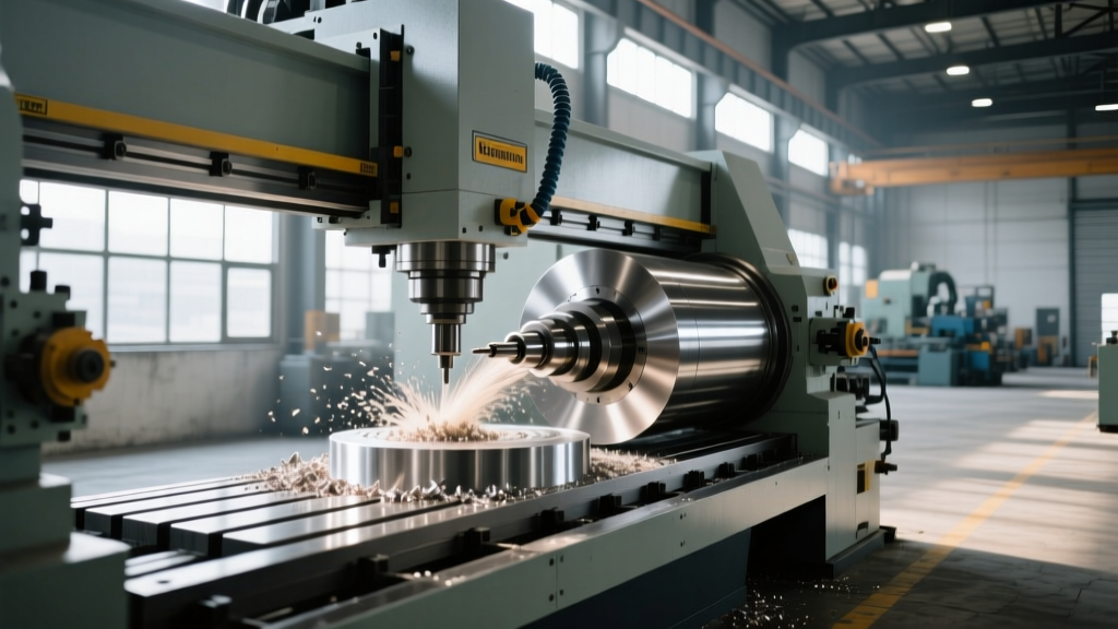
Troubleshooting Extra Large Part Horizontal CNC Machining Finishes
Resolve chatter, thermal drift, and tolerance stack-up in extra large part horizontal CNC machining with this advanced troubleshooting and repair guide.
When executing extra large part horizontal CNC machining on 800mm or 1000mm pallet systems, maintaining an Ra 1.6 µm surface finish and holding geometric flatness within 0.0005 inches across a 40-inch span pushes the physical limits of the machine tool. Large-part horizontal machining centers (HMCs) like the Mazak HCN-8800 or Okuma MA-800H are engineering marvels, but their massive columns, extended Z-axis travels, and heavy workloads introduce complex variables: thermal asymmetry, ballscrew wind-up, and harmonic chatter. This guide provides a diagnostic framework for troubleshooting surface finish degradation and tolerance drift in heavy-duty horizontal production environments.
The Physics of Deflection and Thermal Drift
Surface finish anomalies on large horizontal mills rarely stem from the cutting tool alone. They are usually the result of dynamic structural deflection or thermal growth. As the spindle extends deep into a Z-axis pocket (often exceeding 30 inches of travel), the machine column experiences a forward pitching moment. Simultaneously, the friction from heavy-duty Y-axis and Z-axis ballscrews generates localized heat, causing asymmetric thermal expansion.
Column Sag vs. Spindle Growth
If your bore cylindricity is failing (showing a bell-mouth or taper), you must isolate whether the error is mechanical or thermal. Mechanical sag typically manifests as a consistent, repeatable taper in the same direction, regardless of cycle time. Thermal drift, however, is time-dependent. A bore machined at 8:00 AM will measure differently than one machined at 2:00 PM because the machine's cast iron column has absorbed ambient heat and spindle friction, growing upward and backward by up to 0.003 inches over a 10-hour shift.
Symptom-to-Solution Decision Tree
Use the following diagnostic flow to isolate the root cause of surface finish and tolerance failures during extra large part horizontal CNC machining operations.
- Symptom: Chatter marks (regenerative vibration) on deep Y-axis walls.
- Check 1: Is the tool overhang exceeding 4xD (4 times the diameter)?
- Fix 1A: If yes, switch to a tuned mass damper toolholder (e.g., Sandvik Coromant Silent Tools with a Coromant Capto C8 interface). Standard solid carbide or heavy metal shanks will deflect and chatter at 6xD+.
- Fix 1B: If no, check the spindle speed mapping. Use a tap test or accelerometer to identify the stable chatter-free RPM zones (often between 4,200 and 4,800 RPM for large face mills) and adjust the CAM output accordingly.
- Symptom: Wavy surface finish specifically on X-axis directional moves.
- Check 1: Run a Renishaw Ballbar diagnostic test on the X-axis.
- Fix 1A: If the test shows excessive backlash or reversal spikes, the X-axis ballscrew thrust bearings are likely worn or the pre-tension has relaxed due to thermal cycling. Re-tension the ballscrew to the manufacturer's spec (typically 3°C thermal compensation) and update the CNC backlash compensation parameters.
- Symptom: Flatness drift across the top face of a large prismatic part.
- Check 1: Is the machine equipped with an active thermal compensation sensor array?
- Fix 1A: If yes, verify the thermistors on the column and spindle head are reading within 1°F of the ambient shop temperature. Clean the sensor contacts.
- Fix 1B: Implement an in-cycle Renishaw OMP60 probing routine to touch off a master artifact mounted on the pallet, dynamically shifting the Z-axis work offset (G54.2) before the final finishing pass.
Surface Finish & Tolerance Troubleshooting Matrix
The table below cross-references common defects encountered in heavy horizontal milling with their specific mechanical causes and required interventions.
| Defect Observed | Probable Mechanical Cause | Diagnostic Tool Required | Corrective Action | Target Spec |
|---|---|---|---|---|
| Tapered deep bores (Out of Cylindricity) | Z-axis column pitch under cutting forces | Renishaw XL-80 Laser Interferometer | Adjust pitch error compensation table in the CNC controller; reduce radial depth of cut (RDOC) on finishing passes. | < 0.0008" over 24" depth |
| Poor Ra (Chatter) at pocket floors | Toolholder deflection / lack of damping | Tap testing / Frequency analyzer app | Upgrade to anti-vibration boring bars or damped milling adapters; increase insert edge prep (hone). | Ra 1.6 µm (63 µin) |
| Step mismatches at pallet index (B-axis) | B-axis curvic coupling contamination or unclamp drift | Dial indicator on spindle nose during index | Clean curvic coupling teeth with solvent; check hydraulic clamping pressure (must exceed 1,500 psi for heavy cuts). | < 0.0005" step mismatch |
| Workpiece surface tearing (Built-Up Edge) | Inadequate chip evacuation in horizontal orientation | Visual inspection of cutting zone | Activate 70-bar (1,000 psi) through-spindle coolant; switch to PVD-coated inserts with sharp, positive rake geometries. | Zero BUE, Ra 0.8 µm |
Workholding: Defeating Workpiece Sag on the B-Axis
In extra large part horizontal CNC machining, gravity is your enemy. When a 4,000 lb weldment or casting is mounted on a horizontal tombstone and rotated 90 degrees, the unsupported overhang will sag under its own weight. If you machine the part in this sagged state, the features will be perfectly square to the machine axes, but completely out of square to the part's datum plane once it is unclamped and set upright for inspection.
'The most common mistake in large horizontal machining is treating the fixture like a vertical mill. You cannot just strap the part down. You must use hydraulic floating supports that lock into place only after the part has settled into its natural, gravity-induced resting state against the primary datum locators.' — Senior Manufacturing Engineer, Heavy Equipment Sector.
Actionable Fix: Utilize programmable hydraulic support cylinders (such as those from Roemheld or Hilma) integrated into your tombstone. Program the M-codes to extend the supports, allow them to contact the raw casting, and then lock them hydraulically before the main clamps are engaged. This eliminates induced stress and prevents the part from springing back post-machining, preserving parallelism within 0.001 inches across massive spans.
Coolant Pressure and Chip Evacuation in Deep Cavities
Horizontal machining naturally aids chip evacuation because gravity pulls chips away from the cutting zone. However, when machining deep, enclosed pockets in large parts (such as hydraulic valve bodies or gearbox housings), chips can become trapped, leading to recutting. Recutting destroys surface finish, accelerates insert wear, and introduces localized heat that warps the workpiece.
To maintain an Ra 1.6 µm finish in these scenarios, standard flood coolant is insufficient. You must utilize high-pressure through-spindle coolant (TSC) at a minimum of 70 bar (1,000 psi). The high-pressure jet breaks the chip at the shear zone, preventing long, stringy chips from wrapping around the tool or pooling in the pocket floor. Furthermore, ensure your CAM software utilizes trochoidal milling or dynamic motion toolpaths for deep pockets, which maintains a constant radial engagement and allows the high-pressure coolant to penetrate the cut effectively.
Calibration Protocols and ISO Standards
Troubleshooting is reactive; calibration is proactive. To maintain the tight tolerances required for modern large-part machining, facilities must adhere to rigorous testing standards. The ISO 230 series provides the definitive framework for testing machine tool accuracy. Specifically, ISO 230-2 dictates the methods for determining the accuracy and repeatability of linear and rotary axes.
For shops running extra large part horizontal CNC machining, a quarterly laser interferometer calibration is mandatory, not optional. The massive ballscrews required to move 1000mm pallets are highly susceptible to thermal stretching. By utilizing a laser calibration system, such as the Renishaw XL-80, technicians can map the exact pitch error and thermal growth profile of the X, Y, and Z axes, uploading a compensation grid directly into the CNC controller. This ensures that when the machine commands a move to X+800.000mm, it actually arrives at that exact coordinate, regardless of the thermal state of the ballscrew, securing the geometric integrity of the final part.