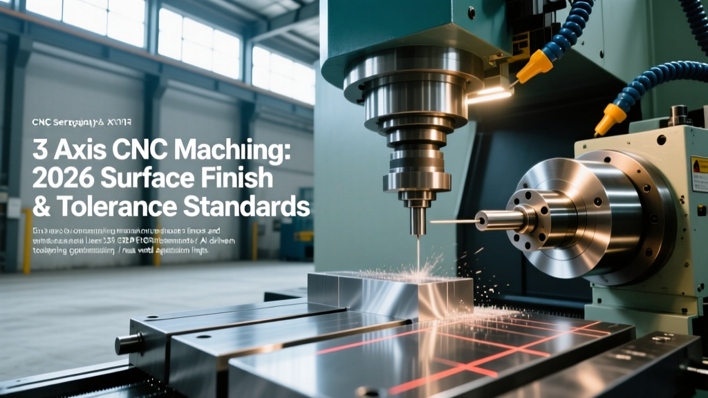
3 Axis CNC Machining: 2026 Surface Finish & Tolerance Standards
Master 3 axis CNC machining tolerances and surface finishes. Explore 2026 GD&T standards, AI toolpathing, and actionable strategies for Ra 0.4 finishes.
The baseline for 3 axis CNC machining has shifted dramatically over the last few years. While legacy machine shops still quote ±0.005" (±0.127mm) as a standard tolerance, modern 3-axis vertical machining centers (VMCs) equipped with in-process probing and AI-driven thermal compensation routinely hold ±0.001" (±0.025mm) without requiring secondary jig grinding. However, achieving these tight tolerances and mirror-like surface finishes requires more than just rigid machine castings; it demands a rigorous understanding of updated metrology standards, tool deflection physics, and advanced GD&T callouts.
The 2026 Tolerance Baseline: Cost vs. Capability Matrix
Specifying tolerances tighter than necessary is the fastest way to inflate manufacturing costs. In modern 3 axis CNC machining, the relationship between tolerance and cost is non-linear. Every time you halve the tolerance band, the cost does not merely double; it scales exponentially due to the requirement for climate-controlled environments, specialized tooling, and reduced material removal rates.
| Tolerance Tier | Range (Inch) | Range (Metric) | Cost Multiplier | Required Technology & Setup |
|---|---|---|---|---|
| Standard | ±0.005" | ±0.127mm | 1.0x (Baseline) | Standard VMC, manual tool setting, standard carbide tooling. |
| Fine | ±0.001" | ±0.025mm | 1.5x | High-speed spindle (12k+ RPM), in-machine Renishaw probing, thermal compensation. |
| Precision | ±0.0005" | ±0.012mm | 2.8x | Climate-controlled shop floor (68°F ±1°), pre-shrunk tool holders, balanced tooling. |
| Ultra-Precision | ±0.0001" | ±0.0025mm | 5.5x+ | Jig boring, post-process CMM verification, active coolant chillers, granite fixtures. |
Surface Finish Metrology: Why Ra is No Longer Enough
For decades, Ra (Arithmetic Average Roughness) was the default metric for specifying surface finishes. However, the adoption of ISO 21920-1:2021 Geometrical Product Specifications has forced the industry to look beyond simple averages. Ra fails to distinguish between a surface with deep scratches and one with high peaks, even if their average roughness is identical.
Expert Insight: The Importance of Rsk (Skewness)When machining bearing journals or hydraulic valve bodies on a 3 axis CNC mill, specify Rsk (Skewness) alongside Ra. A negative Rsk value indicates a surface with more valleys than peaks, which is ideal for oil retention and lubrication. Conversely, a positive Rsk indicates a peak-heavy surface that will wear rapidly under friction, even if the Ra value looks acceptable on paper.
Actionable Workflow: Achieving an Ra 0.4 µm Finish on 6061-T6 Aluminum
Achieving a near-mirror finish (Ra 0.4 µm or 16 µin) on 6061-T6 aluminum using a standard 3 axis CNC machining center requires strict adherence to cutting parameters and tool selection. Built-up edge (BUE) is the primary failure mode here.
- Roughing Pass: Use a 1/2" 3-flulse uncoated carbide end mill. Run at 12,000 RPM, 120 IPM feed rate, 0.25" radial depth of cut (RDOC), and 0.5" axial depth of cut (ADOC). Leave exactly 0.010" of stock on the walls.
- Tool Change & Verification: Switch to a Harvey Tool Diamond-Coated 1/4" end mill. Use a Renishaw OMP600 probe to verify tool length and diameter offset, compensating for any spindle thermal growth that occurred during roughing.
- Finishing Pass: Increase spindle speed to 18,000 RPM. Drop the feed rate to 45 IPM. Set RDOC to 0.005" and ADOC to 0.002".
- Coolant Strategy: Engage flood coolant at a minimum of 300 PSI. High pressure is non-negotiable; it clears the fine aluminum chips from the cutting zone before they can weld to the diamond coating and tear the surface finish.
GD&T Updates: The Death of Concentricity in 3 Axis CNC Machining
One of the most critical updates in modern drafting standards is the official deprecation of the Concentricity symbol. According to the ASME Y14.5 Dimensioning and Tolerancing standard, Concentricity was removed in the 2018 revision because it is mathematically ambiguous and notoriously difficult to verify on a Coordinate Measuring Machine (CMM).
"Designers who still call out Concentricity on 3 axis CNC machining blueprints are forcing machinists to guess the measurement methodology. True Position (⌖) is the only verifiable, mathematically sound callout for coaxial features in modern manufacturing."
Comparison Matrix: True Position vs. Runout on 3-Axis Mills
| GD&T Callout | What it Controls | Best Application in 3-Axis Machining | CMM Verification Difficulty |
|---|---|---|---|
| True Position (⌖) | Location of the feature's center axis relative to datums. | Bolt hole patterns, locating pin bores, and mating interfaces. | Low (Standard CMM routine) |
| Circular Runout (↗) | Combined effect of circularity and coaxiality at a specific cross-section. | Shaft journals, bearing seats, and rotating sealing surfaces. | Medium (Requires V-block or rotary table) |
| Total Runout (↗↗) | Combined effect of cylindricity and coaxiality across the entire surface. | High-speed rotating spindles and precision pump rotors. | High (Requires continuous helical CMM scanning) |
Mitigating Thermal Drift and Tool Deflection
The NIST Advanced Manufacturing Portal frequently highlights thermal drift as the leading cause of out-of-tolerance parts in precision machining. In a 3 axis CNC machining environment, the spindle generates significant heat, causing the Z-axis to expand. On a standard VMC, Z-axis thermal growth can easily exceed 0.002" (0.05mm) over a 4-hour production run.
To combat this without investing in a 5-axis machine with active cooling, shops must implement in-process probing routines. By programming the machine to probe a fixed granite reference artifact every 15 parts, the control can automatically update the Z-axis work offset (G54) to compensate for thermal expansion in real-time.
Warning: Tool Deflection in Deep PocketsWhen machining deep, narrow pockets on a 3-axis mill, tool deflection will ruin your tolerance. A standard 1/4" carbide end mill deflecting just 1 degree under load will push the wall out by 0.004" at a 1.5" depth. Always use long-reach, reduced-shank end mills and employ trochoidal milling toolpaths to maintain constant radial engagement and minimize lateral cutting forces.
Design for Manufacturability (DFM) Checklist for Tight Tolerances
If you are designing parts for 3 axis CNC machining and require tolerances tighter than ±0.001", run your CAD model through this DFM checklist before sending it to the shop floor:
- Avoid Deep, Narrow Pockets: Maintain a depth-to-width ratio of no more than 3:1 for standard end mills. If a 1/4" pocket must be 1.5" deep, expect a 30% cost increase for specialized tooling and extended cycle times.
- Include Tool Relief Grooves: If you require a sharp internal corner at the base of a wall, the part cannot be machined on a 3-axis mill without a secondary EDM operation. Design a dog-bone or T-bone undercut to allow the round end mill to clear the corner.
- Standardize Hole Sizes: Limit your design to standard fractional or letter drill sizes. Specifying a 0.3145" hole requires a custom reamer or an interpolated helical bore, both of which increase cycle time and risk surface finish degradation.
- Specify Datums Logically: Ensure your primary datum (Datum A) is the largest, flattest surface on the part. This provides the most stable clamping surface in the vise and minimizes cosine errors during CMM inspection.
Mastering surface finishes and tolerances in 3 axis CNC machining is no longer about brute-force rigidity; it is about leveraging updated metrology standards, understanding the tribology of surface skewness, and designing parts that respect the physical limitations of rotating cutting tools.