Advanced CNC Machine Engraving: Operator Training Protocols
Master cnc machine engraving with our operator training guide. Learn tooling, feed rates, material holding, and best practices for flawless results.
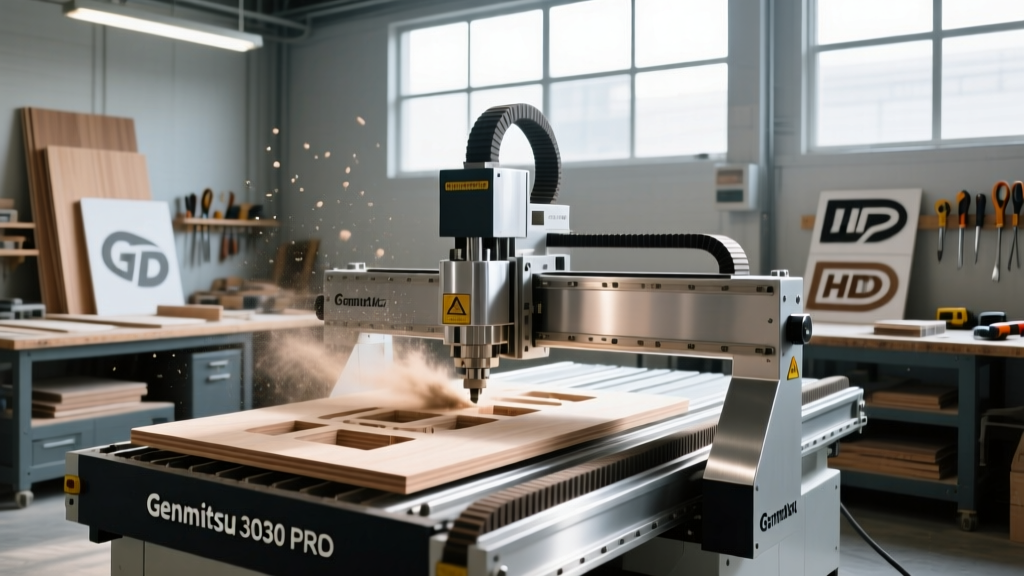
Precision CNC machine engraving demands a radical departure from standard routing protocols. While roughing operations prioritize material removal rates (MRR) and aggressive depth of cut, engraving hinges on minimizing tool deflection, managing sub-thou chiploads, and maintaining absolute workpiece stability. A single micron of spindle runout or a slight variation in material surface flatness can destroy a 60-degree V-bit and ruin a high-value workpiece. This guide establishes rigorous operator training protocols for shops looking to master CNC machine engraving across wood, plastics, and non-ferrous metals.
Tooling Geometry and Runout Tolerances
The foundation of flawless CNC machine engraving is the cutting tool and how it is held. Operators must understand that engraving bits—particularly micro-grain solid carbide V-bits and single-flute engravers—are exceptionally brittle. They lack the core diameter strength of standard end mills, making them highly susceptible to lateral forces.
Selecting the Correct V-Bit Angle
- 60-Degree V-Bits: The standard for fine typography, intricate logos, and detailed map carving. The sharp point penetrates deeply, but the narrow cutting edge requires exceptionally slow feed rates to prevent tip fracture.
- 90-Degree V-Bits: Ideal for deep V-groove signage, chamfering edges, and bold, block lettering. Offers a stronger cutting edge and better chip evacuation than the 60-degree variant.
- 120-Degree and 150-Degree V-Bits: Used primarily for wide background clearing in V-carve toolpaths or creating shallow, broad engravings on acrylic and soft woods.
Operators must measure spindle runout with a dial indicator before running fine engraving jobs. For 1/8-inch shank micro-engravers, total indicated runout (TIR) must not exceed 0.0005 inches. If TIR exceeds 0.001 inches, the tool will effectively cut a wider kerf than its geometry dictates, snapping the tip within the first few inches of the toolpath. Mandate that operators clean ER11 and ER16 collets with isopropyl alcohol and a lint-free cloth before every tool change. According to Harvey Tool's technical support guidelines, improper collet seating and debris are the leading causes of premature micro-tool failure.
Workholding Matrix for Micro-Tolerances
In CNC machine engraving, the Z-axis depth of cut is often measured in thousandths of an inch. If the workpiece shifts, bows, or vibrates, the engraving depth will vary, resulting in uneven line weights and ruined aesthetics. Operators must select workholding methods based on material rigidity and surface area.
| Workholding Method | Best Material Application | Min. Stock Thickness | Operator Limitations & Risks |
|---|---|---|---|
| Universal Vacuum Table | Large format wood, acrylic, MDF | 0.25 inches | Requires 250+ CFM pump; ineffective for small, narrow parts due to lack of surface area suction. |
| Pod and Rail Vacuum | Cabinet doors, solid wood panels | 0.75 inches | Pods must be perfectly aligned to toolpath; risk of cutting into pod seals if Z-zero is miscalculated. |
| Mechanical Toggle Clamps | Thick hardwoods, aluminum billets | 0.50 inches | Clamp pressure can warp thin stock; clamps restrict toolpath boundaries and require clearance zones. |
| Tape and CA Glue Trick | Small plastics, thin brass, delicate inlays | 0.06 inches | Time-consuming to apply; requires specific tape (e.g., XFasten or Nitto) and cyanoacrylate glue. Residue cleanup required. |
The Tape and CA Glue Protocol
For small, intricate engraving jobs on thin stock (like 1/16-inch brass or acrylic nameplates), mechanical clamps will cause deflection, and vacuum tables lack the surface area for suction. Train operators on the tape-and-glue method: Apply high-quality blue painter's tape to the spoilboard and the back of the workpiece. Apply a thin, even bead of medium-viscosity CA (cyanoacrylate) glue to the tape, press the parts together, and activate with a CA accelerator spray. This creates a bond strong enough to withstand lateral engraving forces but allows the part to be popped off cleanly with a putty knife, leaving no residue on the workpiece.
Calculating Feeds, Speeds, and Chipload
Engraving tools require a completely different approach to feeds and speeds compared to standard profiling end mills. The primary goal is to generate a chip thick enough to carry heat away from the cutting edge, but thin enough to prevent tool breakage. This balance is defined by the chipload formula:
Feed Rate (IPM) = Spindle RPM × Number of Flutes × Chip Load (inches per tooth)
According to the CNC Cookbook Router Feeds and Speeds Masterclass, running an engraving bit too slowly causes rubbing, which generates excessive heat, melts plastics, and work-hardens aluminum, leading to immediate tool failure.
Real-World Parameter Examples
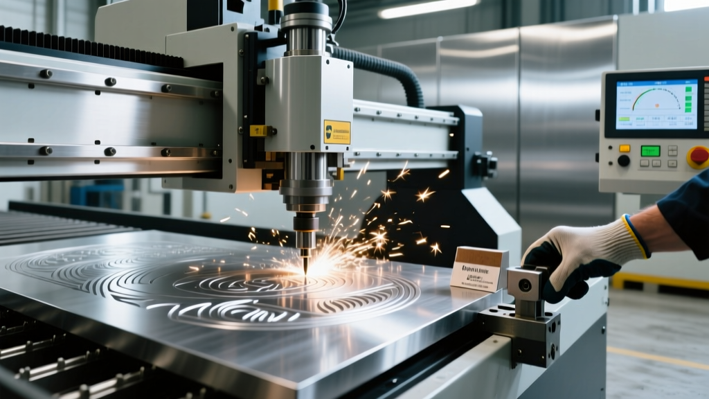
- Engraving 6061-T6 Aluminum: Using a 2-flute, 1/8-inch solid carbide engraver in a 24,000 RPM spindle. Target chipload: 0.0008 inches. Calculation: 24,000 × 2 × 0.0008 = 38.4 IPM. Depth of cut should not exceed 0.010 inches per pass. Use a mist coolant system (like an Unist or AccuLube) to prevent chip welding.
- Engraving Cast Acrylic (PMMA): Using a single-flute, 60-degree V-bit at 18,000 RPM. Target chipload: 0.0015 inches. Calculation: 18,000 × 1 × 0.0015 = 27 IPM. Acrylic requires aggressive chip evacuation; ensure the dust shoe is positioned within 1/8-inch of the material surface to pull fine acrylic dust out of the V-groove, preventing re-welding.
High-frequency spindles (like HSD or Colombo models) require thermal stabilization. Operators must run a 10-minute spindle warm-up routine, starting at 6,000 RPM and stepping up to the target engraving RPM in 2,000 RPM increments. This expands the internal bearings evenly, reducing Z-axis thermal growth that can alter engraving depth by up to 0.005 inches over a long job.
Toolpath Strategies: V-Carve vs. 3D Raster
Operators must be trained to select the correct toolpath strategy in CAM software (such as Vectric VCarve, Fusion 360, or Mastercam) based on the desired visual outcome and material constraints.
V-Carving (Prismatic Engraving)
V-carving utilizes the pointed geometry of a V-bit to vary the width of the cut based on the distance between two vector lines. The tool plunges deeper where vectors are further apart and rises as they converge. This creates a classic, sharp-edged prismatic look. Best practice: Always enable 'Inside Last' or 'Outside Last' profile passes if combining V-carving with a boundary cut, ensuring the V-bit finishes its internal detailing before the part is separated from the holding tabs.
3D Raster Engraving (Photo V-Carve / Greyscale)
For photorealistic engravings on wood or Corian, operators use a greyscale image mapped to Z-axis depth. A small ball-nose or specialized photo-engraving V-bit makes thousands of overlapping lateral passes. Best practice: Stepover must be set extremely tight (8% to 12% of tool diameter). For a 0.030-inch photo V-bit, a stepover of 0.003 inches is mandatory to prevent visible scallop marks. Operators must verify that the machine's acceleration (G-force) settings in the controller are tuned for high-direction-change raster paths to prevent stepper motor stalling or servo following errors.
Standard Operating Procedures (SOP) for Shift Handoffs
Consistency in CNC machine engraving relies on strict adherence to Standard Operating Procedures. When transitioning between jobs or shifts, operators must execute the following pre-flight checklist:
- Z-Axis Calibration: Verify the Z-zero setting using a calibrated auto-zero touch plate. Manually verify the plate thickness with digital calipers to ensure it hasn't worn down from repeated use.
- Material Flatness Check: Run a dial indicator mounted to the spindle across the workpiece surface. If variance exceeds 0.005 inches across the engraving zone, the operator must either surface the material first or apply a 'floating Z' compensation toolpath if the CAM software supports it.
- Dust Collection Verification: Engraving produces fine particulate, not chips. Operators must check the static grounding wire on the dust hose. Fine acrylic or MDF dust can generate static electricity, leading to shocks or, in extreme cases, dust collector fires. Ensure the brush bristles on the dust shoe are intact and making contact with the workpiece.
- Toolpath Simulation: Run a dry-run (air cut) with the Z-axis offset raised by 0.5 inches. Watch the spindle movements at the boundaries to ensure no mechanical clamps or vacuum pods are in the collision path.
By institutionalizing these protocols, machine shops can drastically reduce scrap rates, extend the life of expensive micro-tooling, and deliver the flawless surface finishes that high-end CNC machine engraving demands. For further reading on machine setup and maintenance, operators should consult their specific machine builder's documentation, such as the Carbide 3D Knowledge Base or equivalent OEM resources, to ensure all parameters align with their specific hardware capabilities.
Related reading

Precision Equipment for Tech Manufacturing: CNC Routers, Metrology Tools, and Automation Systems

Operator Injection Molding Essentials: Practical Skills, Safety Protocols, and Machine-Specific Best Practices