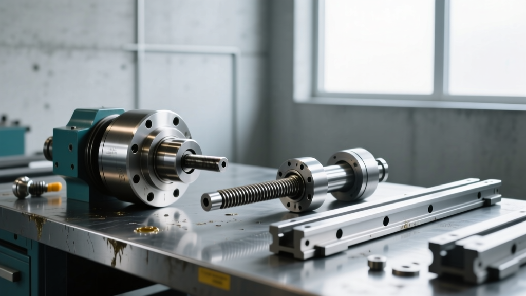
Troubleshooting Failing CNC Machining Components: Repair Guide
Learn how to diagnose and repair failing CNC machining components. Discover root causes of spindle, ball screw, and linear guide failures to reduce downtime.
The True Cost of Component Failure in CNC Mills and Lathes
Unplanned downtime in precision manufacturing remains one of the largest profit killers in 2026. When critical CNC machining components fail unexpectedly, the cost extends far beyond the replacement part. Factoring in lost production, scrapped aerospace or medical parts, and expedited freight for emergency replacements, a single spindle or axis drive failure routinely costs between $350 and $600 per hour per machine. Effective troubleshooting requires moving past generic error codes and directly interrogating the mechanical hardware. This guide provides a field-tested diagnostic framework for identifying, isolating, and repairing the most common mechanical failures in CNC machining centers and lathes.
Symptom-to-Component Diagnostic Matrix
Before tearing down a machine, map the physical symptoms to the likely failing CNC machining components. Use this matrix to narrow your diagnostic focus and avoid unnecessary teardowns.
| Observed Symptom | Primary Suspect Component | Secondary Suspect | Diagnostic Tool Required |
|---|---|---|---|
| High-frequency chatter during finishing cuts | Spindle angular contact bearings | Toolholder taper (CAT/BT) | Accelerometer / Vibration analyzer |
| Axis reversal spikes / lost motion | Ball screw thrust bearings or preload | Servo motor coupling | Tenths-reading dial indicator (0.0001 in) |
| Thermal growth shifting Z-axis zero | Spindle cooling jacket / chiller unit | Ball screw hollow-core cooling | Infrared thermal camera |
| Stick-slip motion at low feed rates | Linear guide blocks (recirculation caps) | Gib adjustment (box ways) | Laser interferometer |
Deep Dive: Spindle Bearing Degradation and Replacement
The spindle is the heart of any CNC mill. Modern high-speed spindles utilize precision angular contact bearings (typically ABEC-7 or ABEC-9 / ISO P4 or P2 class). When these CNC machining components begin to fail, the first indicator is rarely an alarm code; it is a change in the acoustic signature and surface finish of the machined parts.
Identifying the Failure Mode
Spindle bearing failure almost always stems from one of three root causes: grease starvation, contamination, or improper preload. If you are machining aluminum at 12,000+ RPM, grease migration is a primary concern. The centrifugal force pushes the base oil away from the rolling elements, leaving the bearing to run dry and overheat.
⚙️ Technical Spec: For high-speed angular contact bearings (like the SKF 7014 CD/P4A series), the industry standard lubricant is Klüber Isoflex NBU 15. The bearing cavity should only be filled to 10-15% of its free space. Over-greasing causes rapid temperature spikes due to fluid friction, leading to immediate cage failure.The Spindle Run-In Procedure
If you are replacing spindle bearings in-house or reinstalling a rebuilt cartridge, a strict run-in procedure is non-negotiable. Skipping this step will destroy $4,000 worth of precision bearings in under an hour.
- Start the spindle at 10% of its maximum rated RPM.
- Monitor the spindle housing temperature using a contact thermocouple or IR gun. The temperature must not rise more than 5°C (9°F) every 10 minutes.
- If the temperature stabilizes below 55°C (131°F), increase the speed by 10% increments every 15 minutes.
- If the temperature exceeds 65°C (149°F) at any point, immediately halt the spindle, allow it to cool to ambient room temperature, and restart the process. This indicates excess grease or excessive preload.
For comprehensive manufacturer specifications on precision bearing tolerances and mounting protocols, refer to the SKF Machine Tools Industry Solutions documentation.
Ball Screw Backlash: Measurement and Preload Adjustment
Backlash in the X, Y, or Z axes manifests as circular interpolation errors (often visible as witness lines or 'dogs' on bored holes). While CNC controllers offer software backlash compensation, relying on it is a temporary band-aid that masks failing CNC machining components. You must address the mechanical root cause.
Step-by-Step Backlash Isolation
To determine if the backlash is in the ball screw assembly or the servo coupling, perform this physical test:
- Mount a tenths-reading dial indicator (0.0001 inch resolution) on the machine table, with the stylus pressing against the spindle nose or column.
- Command the axis to move in the positive direction by 0.1000 inches at a slow feed rate (e.g., 10 IPM).
- Stop the machine. Zero the dial indicator.
- Command a negative move of 0.0010 inches.
- Observe the dial indicator. If the indicator does not move exactly 0.0010 inches, you have mechanical backlash.
- Now, command a negative move of 0.0500 inches. If the first 0.0020 inches of commanded movement yields zero physical movement on the dial, your total backlash is 0.0020 inches.
Adjusting Double-Nut Preload
Many heavy-duty CNC lathes and mills utilize double-nut ball screw assemblies (such as the NSK BSS or THK BIF series) where preload is maintained by a physical shim between the two nuts. To increase preload and eliminate backlash, you must remove the assembly, measure the existing shim with a micrometer, and have a new shim ground that is thicker by exactly 0.0002 to 0.0004 inches. Increasing shim thickness by more than 0.0005 inches will cause excessive rolling friction, leading to servo motor overload alarms and rapid screw degradation. For detailed maintenance and preload specifications, consult the NSK Precision Ball Screws engineering catalog.
Linear Guide Block Contamination and Seal Upgrades
Profile rail linear guides (like the ubiquitous Hiwin HG or THK SRG series) are highly rigid but extremely vulnerable to chip ingress and coolant washout. When a linear guide block begins to exhibit stick-slip motion or emits a grinding noise, the recirculation caps are likely packed with abrasive swarf.
Upgrading Wiper Seals for Harsh Environments
Standard linear guide blocks come equipped with basic polyurethane end seals. If you are machining cast iron, abrasive composites, or stringy materials like titanium, these standard seals will fail within months. Upgrading your CNC machining components to specialized scraper seals is a high-ROI modification.
- Metal Scrapers (ZZ type): Essential for cast iron and heavy forging scale. They physically scrape large, abrasive chips away before they reach the polymer seals.
- Double-Lip Scrapers (KK type): Best for sticky aluminum and heavy flood coolant environments. The secondary lip retains the grease inside the block while the primary lip wipes away fine particulate.
- Low-Profile Blocks: If Z-axis clearance is an issue, switching from standard flange blocks to low-profile square blocks (e.g., Hiwin HGH20CA) can improve rigidity while allowing for custom sheet-metal way cover integration.
When rebuilding a contaminated linear guide block, do not simply flush it with WD-40 or standard solvent. Disassemble the end caps, remove the recirculation tubes, and clean the internal raceways with non-chlorinated brake cleaner. Repack the block with the manufacturer-specified lithium-complex grease (e.g., Mobilux EP2) before reassembly. Further guidance on seal configurations and block maintenance can be found via THK Linear Guide Systems.
Way Cover and Bellows Degradation
While not a moving component themselves, way covers are the first line of defense for your linear guides and ball screws. Polyurethane (PU) bellows are standard on most mid-range CNC mills, costing roughly $120 to $200 per axis. However, in high-heat environments (like dry machining Inconel or heavy steel milling), PU covers melt, tear, and allow hot chips to drop directly onto the linear rails.
Upgrading to Kevlar-reinforced or aluminum-slat way covers costs between $450 and $800 per axis. While the upfront cost is higher, the prevention of a single $6,000 linear rail replacement justifies the upgrade immediately. Inspect way covers weekly; if the internal support springs are failing, the cover will sag and trap chips against the wiper seals of the linear blocks.
Preventative Maintenance Framework for Critical Components
To maximize the lifespan of your CNC machining components, implement this strict, interval-based maintenance schedule. Do not rely on operator memory; integrate these checks into your shop's digital CMMS (Computerized Maintenance Management System).
- Daily (Operator Level): Wipe down linear guide wiper seals exposed on the table. Check spindle chiller fluid level and verify the coolant temperature is holding within ±1°C of the ambient room temperature.
- Weekly (Setup/Tech Level): Inspect way covers for sagging or tears. Clean the spindle taper with a specialized no-lint cloth and isopropyl alcohol; check for fretting corrosion on the retention knobs.
- Bi-Annually (Maintenance Level): Check ball screw thrust bearing preload using the dial indicator method outlined above. Re-grease linear guide blocks via the zerk fittings (use exactly 3-5 strokes of the manual grease gun per block; over-greasing will blow out the end seals).
- Annually (Specialist Level):Perform a full ballbar test (using a Renishaw QC20-W or similar) to plot circularity errors and isolate specific axis reversal spikes. Check hydraulic drawbar pressure to ensure it meets the OEM spec (typically 35-40 bar for CAT40/BT40 spindles).