Quick Tips for CNC Machined Parts With Undercuts: Tooling & Design
Master re-entrant features with quick tips for CNC machined parts with undercuts. Explore L/D ratios, lollipop cutter specs, and 5-axis collision avoidance.
The Geometry Conflict: Shank vs. Workpiece
An undercut in CNC machining is defined as a re-entrant feature—a geometry where the cross-section of the machined cavity is larger than its opening. Standard end mills cannot access these features because the tool shank or holder collides with the workpiece before the cutting edges reach the target depth. Executing these features requires specialized tooling, multi-axis kinematics, or aggressive design modifications. Understanding the physical limitations of cutting tool reach is the first step in producing high-tolerance undercut parts without catastrophic tool failure.
Specialized Tooling Specifications & Selection
When 3-axis machining is mandated, shops must rely on tools with reduced neck diameters. The most common solutions are undercutting end mills (lollipop cutters), slot cutters, and T-slot end mills. Selecting the right geometry depends on the required sweep angle and the material being machined.
| Tool Type | Typical Sweep | Neck/Cutting Ratio | Max Reach (L/D) | Avg. Cost (Carbide) |
|---|---|---|---|---|
| Lollipop (Undercut) End Mill | 220° to 270° | 1:2 (Neck is half of cutting dia.) | 8:1 to 12:1 | $85 - $140 |
| Slot Cutter / Arbor Style | 360° (Disc) | 1:3 to 1:5 | 4:1 to 6:1 | $120 - $250 (w/ inserts) |
| T-Slot End Mill | N/A (Specific profile) | 1:1.5 | 3:1 to 5:1 | $60 - $110 |
For complex internal contours, manufacturers like Harvey Tool offer undercutting end mills with 270° spherical sweeps and AlTiN coatings, allowing for deep O-ring grooves and internal interlocking joints in hardened steels. A common specification for precision aerospace work is a 1/8-inch cutting diameter with a 1/16-inch neck diameter and a 1-inch reach.
Warning: Chip Evacuation in Blind UndercutsRe-entrant features naturally trap chips. When machining blind undercuts in gummy materials like 6061 Aluminum or 316 Stainless Steel, secondary chip cutting will destroy the tool. You must utilize through-tool high-pressure coolant (minimum 1000 PSI / 69 bar) or program aggressive air-blast peck cycles to clear the cavity. Flood coolant alone will not penetrate the cutting zone of a deep undercut.
The Physics of Tool Deflection
The primary enemy of undercut machining is tool deflection. Because the neck diameter of a lollipop cutter is significantly smaller than its cutting diameter, the tool acts as a cantilever beam. According to beam deflection theory, deflection ($\delta$) increases with the cube of the overhang length ($L^3$).
The Cubic Rule of Reach: If you double the reach of your undercutting tool while maintaining the same neck diameter and cutting force, the tool will deflect eight times further. This is why minimizing reach is the most critical quick tip for CNC machined parts with undercuts.
To counteract this, machinists must reduce radial engagement. When machining a 1/8-inch undercut with a 1-inch reach in 4140 steel, do not attempt a full-width slotting pass. Instead, use a trochoidal or dynamic milling toolpath that limits the radial depth of cut (RDOC) to 5% to 10% of the tool diameter. This drastically reduces the lateral cutting forces that cause the neck to bend and chatter against the workpiece wall.
Climb vs. Conventional Milling in Re-entrant Features
Standard CNC doctrine dictates climb milling for superior surface finish and tool life. However, deep undercuts present a unique edge case. In climb milling, the cutting forces pull the tool into the workpiece. If the tool neck is highly flexible (L/D ratio > 8:1), this pulling force can induce severe harmonic chatter, resulting in a poor surface finish and premature edge chipping.
Switching to conventional milling reverses the force vector, pushing the flexible tool neck away from the workpiece wall. While this may leave a slightly rougher surface finish and accelerate flank wear, it stabilizes the cut and prevents the catastrophic vibration that shatters carbide necks. Test both directions on a scrap part; if chatter marks appear on the undercut wall during climb milling, reverse the spindle rotation and toolpath direction.
5-Axis Kinematics vs. 3-Axis Extended Reach
Before purchasing $400 worth of fragile, extended-reach specialty tooling, evaluate whether 5-axis simultaneous machining or a 3+2 positional setup can solve the geometry conflict. By tilting the B or C axis, a standard, rigid 4-flute end mill can access re-entrant features from an angled approach.
Decision Matrix: Tooling vs. Multi-Axis Setup
- Use 3-Axis + Specialty Tooling When: The undercut is a simple 2D profile (like a standard O-ring groove or a T-slot), the batch size is high (justifying the tooling cost), and the machine lacks a trunnion table or swivel head.
- Use 3+2 Positional 5-Axis When: The undercut is localized to a specific angled face. Locking the axes and using a short, rigid end mill eliminates deflection entirely and reduces cycle time compared to delicate 3-axis passes.
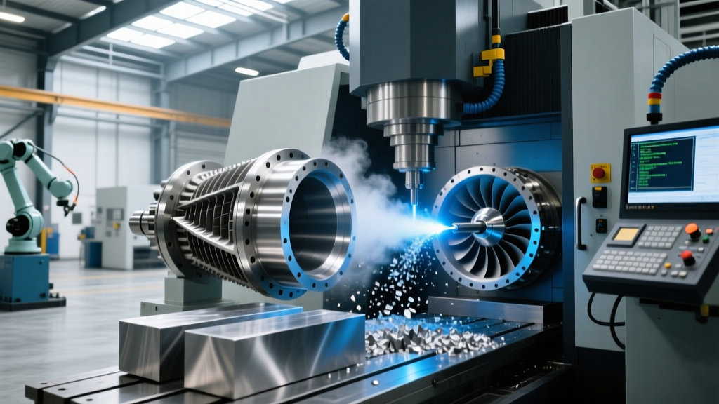
- Use Simultaneous 5-Axis When: The undercut features complex 3D contours (e.g., impeller roots or sculpted aerospace ducting) where a fixed-angle lollipop cutter would leave cusps or require manual blending.
While 5-axis machine time commands a higher hourly shop rate (often $150–$220/hr compared to $85–$110/hr for 3-axis), the elimination of custom tooling lead times, the reduction in scrap from broken tools, and the superior surface finish often make it the more cost-effective choice for low-to-medium volume production.
Design for Manufacturability (DFM) Alternatives
The most effective quick tip for CNC machined parts with undercuts is to design them out entirely. If an undercut is specified for an assembly function, consider these DFM modifications to reduce machining costs by up to 40%:
- Part Splitting and Dowel Pins: Instead of machining a complex internal interlocking undercut, split the part into two halves. Machine standard 2.5D pockets and use hardened ANSI standard dowel pins (e.g., 1/4-inch diameter, press-fit) to align and join the halves. A $0.15 dowel pin saves hundreds of dollars in 5-axis machining time.
- Face Grooves over Internal Grooves: If the undercut is intended for a seal or O-ring, redesign the mating part so the groove is cut into a flat, accessible face rather than an internal, blind bore.
- Radii and Relief Cuts: Ensure that the entrance to any necessary undercut features a generous lead-in radius. A sharp 90-degree internal corner at the entrance of an undercut forces the tool to engage fully and abruptly, spiking cutting forces and breaking the neck. A 0.030-inch lead-in chamfer or radius allows for smooth tool entry.
For comprehensive data on milling formulas, cutting forces, and tool deflection management, refer to the technical knowledge bases provided by industry leaders like Sandvik Coromant. Mastering the intersection of tool geometry, machine kinematics, and part design is the only way to reliably produce undercut features at scale.