How CNC Machined Components Manufacturers Optimize Aerospace Yields
Discover how leading CNC machined components manufacturers optimize aerospace yields using 5-axis tooling, zero-point workholding, and strict QA protocols.
Aerospace production tolerances have tightened significantly, with critical flight-control components now routinely demanding geometric dimensioning and tolerancing (GD&T) profiles held to ±0.0002 inches. For CNC machined components manufacturers serving this sector, achieving these specs while maintaining profitability requires moving beyond standard 3-axis milling and generic toolholding. The shift toward high-mix, low-volume production in 2026 mandates advanced spindle interfaces, automated workholding, and in-machine metrology. According to NASA's Advanced Manufacturing initiatives, integrating smart machining and adaptive control is now a baseline requirement for Tier 1 and Tier 2 aerospace suppliers.
The Material Challenge: Machining Inconel 718 and Ti-6Al-4V
Aerospace applications heavily rely on nickel-based superalloys and titanium alloys due to their high strength-to-weight ratios and thermal resistance. However, these materials are notoriously hostile to cutting tools. Inconel 718 work-hardens rapidly and generates extreme heat at the shear zone, while Ti-6Al-4V (Grade 5 Titanium) has poor thermal conductivity, forcing heat directly into the cutting edge.
Critical Machining Parameters for Aerospace Alloys:- Inconel 718 Roughing: 120-150 SFM, 0.003-0.005 IPT, utilizing AlTiN or TiAlN coated solid carbide endmills with variable helix angles to disrupt harmonics.
- Ti-6Al-4V Finishing: 250-300 SFM, 0.002 IPT, requiring high-pressure through-tool coolant (minimum 1,000 PSI) to evacuate stringy chips and prevent re-welding.
- Tool Life Expectancy: Typically 45-90 minutes of active cut time before flank wear exceeds 0.008 inches, necessitating automated tool breakage detection.
Case Study 1: 5-Axis Simultaneous Milling for Turbine Impellers
A mid-sized supplier of aerospace fluid-system components faced a 14% scrap rate when machining complex Inconel impellers. The primary failure mode was tool deflection during deep-cavity finishing, resulting in out-of-tolerance profile deviations on the impeller blades. The root cause was traced to the use of standard CAT40 toolholders, which exhibited Total Indicator Runout (TIR) of 8-12 microns at the tool nose.
Tooling and Spindle Interface Upgrades
The manufacturer transitioned to HSK-A63 spindle interfaces equipped with high-precision hydraulic chucks. The HSK-A63 system provides dual contact (face and taper), ensuring axial repeatability within 2 microns even under heavy radial loads. By pairing this with shrink-fit toolholders for long-reach finishing operations, the TIR was reduced to less than 3 microns.
| Metric | Previous Setup (CAT40) | Optimized Setup (HSK-A63 + Shrink-Fit) |
|---|---|---|
| Tool Nose TIR | 8 - 12 µm | < 3 µm |
| Scrap Rate | 14.2% | 1.8% |
| Cycle Time (Finishing) | 48 minutes | 36 minutes (Higher feed rates enabled) |
| Toolholder Investment | $180 / holder | $650 / holder |
While the initial capital expenditure for HSK toolholders and the induction heating unit was approximately $38,000, the reduction in scrapped Inconel forgings (which cost upwards of $1,200 each in raw material alone) yielded a full return on investment in under four months.
Case Study 2: Zero-Point Clamping Systems for High-Mix Production
For CNC machined components manufacturers producing landing gear actuators and structural brackets, setup time is a major bottleneck. Traditional vise setups require manual dialing, indicating, and torquing, often taking 45 to 60 minutes per fixture change. To combat this, leading shops are adopting zero-point clamping systems (such as those from System 3R or LANG Automation).
Calculating the ROI on Zero-Point Workholding
Zero-point systems utilize pneumatically or hydraulically actuated base plates mounted directly to the machine table. Fixture plates are pre-loaded with parts offline and dropped into the base plate, achieving repeatability of 0.002mm (0.00008 inches) with a pull-down force exceeding 40,000 Newtons.
ROI Breakdown: Zero-Point System Integration- Average Setup Time Reduction: From 45 minutes to 2 minutes per operation.
- Setups per Day: 4 fixture changes.
- Time Saved Daily: 172 minutes (2.86 hours).
- Fully Burdened Labor Rate: $85 / hour.
- Daily Savings: $243.10.
- Annual Savings (250 working days): $60,775.
- System Cost (Base plates, pallets, pneumatic pump): $28,500.
- Payback Period: 5.6 months.
Beyond the direct labor savings, zero-point systems drastically reduce spindle idle time. According to NIST's Advanced Manufacturing research, maximizing spindle utilization is one of the most effective levers for improving overall equipment effectiveness (OEE) in discrete manufacturing environments.
In-Machine Probing and Thermal Stability
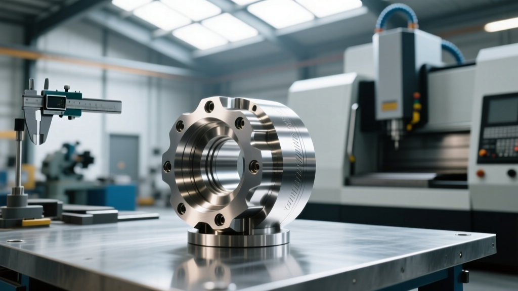
Aerospace components cannot rely solely on post-process CMM (Coordinate Measuring Machine) inspection, as scrapping a near-finished part represents a massive loss of machine time and material. Top-tier CNC machined components manufacturers integrate high-accuracy touch-trigger probes (like the Renishaw OMP60 or Blum TC76) directly into the spindle.
These probes perform in-cycle gauging, allowing the CNC control to automatically update tool offsets if thermal growth or tool wear causes dimensional drift. For example, when boring a critical 2.5000-inch bearing journal in 7075-T6 aluminum, the probe measures the bore after the semi-finishing pass. If the bore measures 2.4985 inches, the control automatically shifts the X and Y axes by 0.00075 inches for the final spring pass, guaranteeing the final dimension without operator intervention.
Compliance with AS9100 Rev D requires documented evidence of process control and measurement traceability. In-machine probing provides the automated data logs necessary to satisfy stringent First Article Inspection (FAI) and PPAP requirements, as outlined by FAA production approval guidelines.
Decision Framework: Evaluating CNC Machined Components Manufacturers
When sourcing critical aerospace or medical parts, procurement engineers must look beyond quoted price per piece. The capability of the shop floor infrastructure dictates long-term yield and supply chain reliability. Use the following matrix to evaluate potential manufacturing partners.
| Evaluation Criteria | Minimum Acceptable Standard | World-Class Indicator |
|---|---|---|
| Spindle Technology | CAT40 / BT40 with standard ER collets | HSK-A63 / Capto C6 with hydraulic/shrink-fit holders |
| Coolant Delivery | 300 PSI through-tool | 1,000+ PSI programmable through-tool + external air blast |
| Metrology Equipment | Manual CMM and optical comparators | 5-axis scanning CMM, CT scanning, and in-machine probing |
| Workholding | Standard Kurt vises and manual toe clamps | Zero-point automation, custom hydraulic tombstones |
| Quality Certifications | ISO 9001:2015 | AS9100 Rev D, Nadcap accredited for special processes |
The Hidden Cost of Low-Tier Tooling
A common mistake in supplier selection is choosing a manufacturer based on the lowest initial quote, only to discover they utilize low-cost, generic tooling. Cheap carbide endmills lack the consistent substrate grain structure and precise edge prep (such as edge honing to 2-4 microns) required to machine aerospace superalloys. This results in premature chipping, unpredictable tool life, and ultimately, micro-fractures or work-hardened surfaces on the finished component that will fail fatigue testing. Always audit the manufacturer's tooling crib and verify their partnerships with premium cutting tool brands like Sandvik Coromant, Kennametal, or Walter.
Optimizing yield in aerospace machining is not an accident; it is the direct result of capital investment in rigid machine architectures, precision workholding, and uncompromising metrology. By demanding these technical standards from your supply chain, you ensure that the CNC machined components you integrate into your final assemblies meet the extreme operational demands of modern flight.