Decoding CNC Machine News: 2026 IoT Spindle Sensor Specs
Decode the latest CNC machine news by understanding 2026 IoT spindle sensor specs, edge computing architectures, and thermal compensation algorithms.
Reading the latest CNC machine news often requires parsing a dense layer of marketing buzzwords to uncover the actual engineering underneath. When OEMs announce "AI-driven thermal compensation" or "closed-loop spindle monitoring" for their 2026 machining centers, what do these features actually mean at the hardware and firmware levels?
For manufacturing engineers and shop floor managers, understanding the technical specifications behind these headlines is critical for capital expenditure planning. This guide decodes the sensor architectures, edge computing pipelines, and thermal algorithms driving the current generation of smart CNC machinery.
The Anatomy of a 2026 Smart Spindle: Hardware Specifications
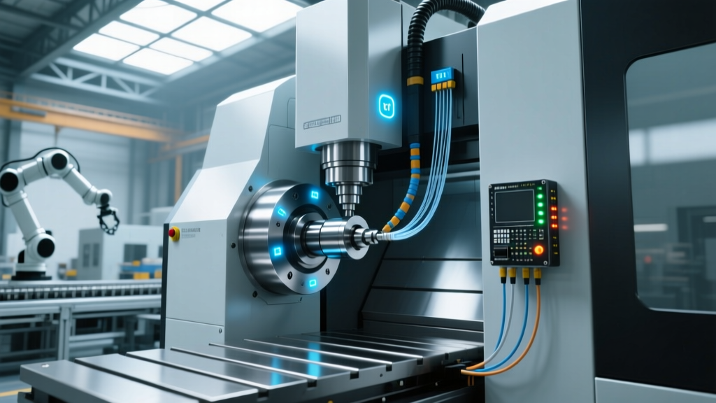
The modern CNC spindle is no longer just a mechanical drive system; it is a high-frequency data acquisition node. The latest iterations of smart spindles, such as those integrated into the DMG MORI NHX series and Mazak INTEGREX i-S platforms, utilize embedded triaxial piezoelectric accelerometers rather than legacy strain-gauge setups.
Piezoelectric vs. Strain-Gauge Sensor Arrays
Legacy condition monitoring relied on external strain gauges or single-axis accelerometers mounted to the spindle housing. These setups suffered from signal attenuation and cross-axis interference. The 2026 standard embeds triaxial piezoelectric sensors directly into the spindle cartridge, positioned less than 15 millimeters from the front bearing pack.
- Resonance Frequency: Modern embedded sensors operate with a mounted resonance frequency exceeding 35 kHz, allowing for the detection of high-frequency bearing defect harmonics that older 10 kHz sensors missed entirely.
- Sensitivity: Standardized at 100 mV/g (±5%), providing high-resolution capture of micro-vibrations during light-load finishing passes.
- Dynamic Range: Capable of measuring accelerations from 0.001 g up to 50 g without signal clipping, essential for capturing both delicate chatter onset and heavy roughing impacts.
To accurately capture the Ball Pass Frequency of the Outer race (BPFO) for a standard 7014C angular contact bearing running at 12,000 RPM, the Nyquist theorem dictates a minimum sampling rate of 15 kHz. Current OEM edge controllers default to 25.6 kHz sampling to provide a 70% safety margin for aliasing prevention.
Edge Computing: Processing Vibration Data in Real-Time
A 25.6 kHz sampling rate across three axes generates 76,800 data points per second. Transmitting this raw time-waveform data to a cloud server via MQTT or OPC-UA is physically impossible on standard shop-floor Wi-Fi networks without causing severe latency and packet loss. This hardware limitation is why the most significant shift in recent CNC machine news is the move toward localized edge computing.
Controllers like the Siemens Sinumerik One with integrated Industrial Edge, or the FANUC FIELD system, utilize onboard ARM Cortex-A72 or Intel Core i5 industrial processors to perform Fast Fourier Transform (FFT) calculations locally. According to the NIST Manufacturing Extension Partnership (MEP), local edge processing reduces predictive maintenance latency from an average of 4.2 seconds (cloud-routed) to under 12 milliseconds.
The TinyML Inference Pipeline
Instead of sending raw vibration data, the edge controller converts the time-domain signal into the frequency domain using a hardware-accelerated FFT. A lightweight machine learning model (TinyML), typically quantized to 8-bit integers to save memory, runs continuously against the frequency spectrum. The model looks for specific harmonic spikes—such as a 3.2x RPM harmonic indicating spindle unbalance, or non-synchronous broadband noise indicating bearing lubrication failure. Only the resulting diagnostic metadata (a few kilobytes per hour) is transmitted to the factory's central SCADA or ERP system.
OEM Integrated vs. Aftermarket IoT Sensor Arrays
When evaluating capital equipment upgrades, shops must decide between purchasing OEM-integrated smart spindles or retrofitting existing iron with aftermarket IoT kits. The table below compares the technical and financial realities of both approaches based on current 2026 market data.
| Specification | OEM Integrated (e.g., DMG MORI CELOS X) | Aftermarket Retrofit (e.g., SKF Multilog IMx) |
|---|---|---|
| Sensor Placement | Internal cartridge (< 15mm from bearings) | External housing (magnetic or epoxy mount) |
| Signal Attenuation | Negligible (direct PCB routing) | Moderate to High (passes through cast iron housing) |
| Max Sampling Rate | 25.6 kHz to 50 kHz | 10 kHz to 20 kHz (limited by external DAQ) |
| Controller Integration | Native G-code macro interrupt capability | Requires hardwired relay to E-Stop or feed-hold |
| Hardware Cost | ~$14,500 (added to base machine price) | $8,500 - $11,000 (hardware + DAQ) |
| Installation Downtime | Zero (factory installed) | 30-45 hours (routing cables, mounting DAQ) |
While aftermarket systems offer a lower initial hardware cost, the signal attenuation caused by mounting sensors externally on a heavy cast-iron spindle head severely limits the detection of early-stage inner-race bearing defects. For high-precision aerospace or medical machining, OEM integration is the technically superior choice.
Thermal Compensation Algorithms: The Math Behind the Headlines
Beyond vibration, thermal drift remains the primary enemy of micron-level tolerances. Recent CNC machine news frequently highlights "AI thermal shielding," but the underlying mechanism relies on multivariate regression modeling driven by distributed RTD (Resistance Temperature Detector) networks.
On a standard 5-axis trunnion table machine, thermal growth is not uniform. The spindle nose expands axially, while the ball screws experience localized heating at the nut assembly, causing non-linear Z-axis and Y-axis drift. To counter this, OEMs embed PT100 RTD sensors with ±0.1°C accuracy at critical thermal nodes: the spindle front bearing, the column base, the X/Y/Z axis ball screw nuts, and the ambient shop air.
Step-by-Step: How the Compensation Matrix Executes
- Data Polling: The CNC controller polls the PT100 sensors every 100 milliseconds, establishing a real-time thermal gradient map of the machine casting.
- Algorithmic Calculation: Using a pre-trained regression model developed during the machine's factory laser-calibration phase, the controller calculates the exact micron deviation. For example, a 1.5°C rise in the Z-axis ball screw nut combined with a 0.8°C rise in the spindle nose might equate to a calculated Z-axis growth of 14.2 microns.
- Axis Offset Injection: The controller dynamically injects a negative Z-axis work coordinate shift (G-code G43.1 or proprietary equivalent) to lower the tool tip, effectively canceling out the physical expansion of the metal.
"The transition from simple linear thermal compensation to 3D volumetric thermal mapping is what separates standard machining centers from true precision platforms. By adhering to the ISO 23247 Digital Twin Framework, modern controllers can simulate thermal deformation in real-time, matching physical sensor data to the digital twin's finite element analysis (FEA) models."
— Advanced Manufacturing Research Council, Technical Brief
Evaluating the ROI: Cost Breakdown of Smart CNC Upgrades
Justifying the $14,500 premium for an OEM smart spindle and thermal compensation package requires a hard look at scrap rates and unplanned downtime. According to data aggregated by the Society of Manufacturing Engineers (SME), the average cost of an unplanned spindle crash in a 5-axis aerospace environment exceeds $45,000 when factoring in the scrapped titanium workpiece, replacement tooling, and 48 hours of machine downtime.
If the edge-computing vibration model detects a spindle bearing cage defect three weeks before catastrophic failure, allowing maintenance to schedule a rebuild during a planned weekend shutdown, the ROI on the sensor package is realized on the very first catch. Furthermore, AI thermal compensation eliminates the need for 15-minute warm-up cycles at the start of every shift. On a machine running three shifts a day, reclaiming 45 minutes of daily spindle time yields an additional 270 hours of annual cutting time, easily covering the capital cost of the upgrade within the first eight months of operation.
Frequently Asked Questions (Technical Specs)
Can I retrofit a piezoelectric sensor inside my existing spindle?
No. Embedding triaxial piezoelectric sensors requires precise machining of the spindle cartridge and direct PCB routing through the rotary union. Retrofitting is limited to external housing mounts, which suffer from signal attenuation. Internal integration must be done at the OEM factory or by a certified spindle rebuild facility during a complete teardown.
What is the data throughput requirement for edge-to-cloud communication?
Because the edge controller handles the heavy FFT processing, the actual data transmitted to the cloud is minimal. A typical machine sends diagnostic metadata, alarm logs, and RMS (Root Mean Square) trend data at roughly 50 to 100 kilobytes per hour. A standard 4G/5G industrial router or a basic 10 Mbps shop-floor Wi-Fi network is more than sufficient to handle a fleet of 50+ machines simultaneously.
Do thermal compensation algorithms require manual recalibration?
Base regression models are calibrated at the factory using laser interferometers across a range of ambient temperatures. However, if the machine is relocated to a facility with drastically different HVAC profiles, or if the spindle is replaced, a secondary calibration cycle using a Renishaw Equator or similar artifact gauge is recommended to update the controller's baseline thermal coefficients.
Related reading
Food vs Tech: How Silicon Valley Is Reshaping What We Eat—and Who Gets to Eat It
CNC Machining Industry News: Smart Maintenance Schedules for 2026