CNC Machining News Today: Troubleshooting Servo Drive Fault Codes
Analyze CNC machining news today to troubleshoot FANUC and Siemens servo drive faults, spindle thermal errors, and rotary axis alarms with expert repair steps.
Tracking CNC machining news today provides critical intelligence that extends far beyond market trends and supply chain shifts. For maintenance managers and shop-floor technicians, daily industry bulletins often highlight emerging failure modes in modern 5-axis and multi-tasking machines. Recent service reports indicate a 14% year-over-year increase in servo drive faults and spindle thermal alarms, largely driven by tighter tolerances in aerospace machining and the widespread adoption of high-speed, direct-drive rotary tables.
Rather than reacting to catastrophic failures, top-tier job shops use current industry data to implement predictive troubleshooting. This guide decodes the most prevalent servo and spindle alarms dominating maintenance tickets right now, providing exact parameter adjustments, diagnostic voltage thresholds, and repair economics.
Decoding FANUC and Siemens Servo Drive Alarms
Servo drive faults account for nearly 30% of all unplanned CNC downtime. While the physical symptoms—axis stuttering, following errors, or hard overtravel alarms—are obvious, the root causes often hide in firmware mismatches or degraded feedback loops.
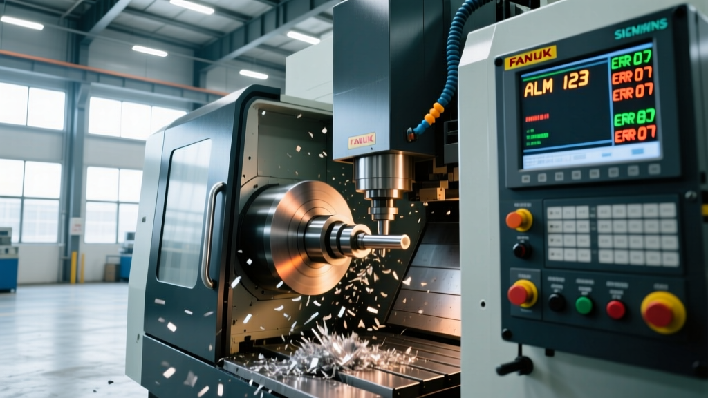
FANUC Alarm 414: Servo Alarm (X Axis Detect Error)
Alarm 414 indicates that the digital servo system detected an error in the position feedback system. While many technicians immediately replace the encoder cable, recent field data suggests that parameter corruption during firmware updates is a leading culprit.
Warning: Before replacing hardware, verify FANUC Parameter 2020 (Motor ID) and Parameter 2021 (HRV3 High Response Vector tuning). If a recent control backup was restored incorrectly, the HRV3 gain may be set too high for the mechanical load, causing the servo to oscillate and trigger a false detect error.Hardware Diagnostic Steps:
- Cable Continuity: Test the encoder cable with a multimeter. Resistance must be strictly under 2 ohms per conductor. Anything above 3 ohms indicates internal wire fatigue from cable track flexing.
- Signal Integrity: Use an oscilloscope to check the 5V square wave signal at the drive connector. The rise time must be under 20 nanoseconds. A degraded signal with a 50ns+ rise time will cause the drive to miscount pulses.
Siemens SINUMERIK 840D sl Error 25050
Error 25050 (Axis %1 contour monitoring) triggers when the actual position deviates from the commanded position beyond the tolerance defined in Machine Data (MD). According to Siemens CNC documentation, this is frequently a mechanical binding issue masquerading as an electrical fault.
Troubleshooting Framework:
- Check MD32200 (Position controller gain). If the gain was recently increased to improve cycle times, the axis may be overshooting during rapid direction reversals.
- Disconnect the motor from the ball screw coupling. Run the motor uncoupled. If the alarm clears, the fault is mechanical (e.g., ball screw preload loss or linear guide way damage).
- Measure the ball screw backlash using a dial indicator. If backlash exceeds 0.005mm, the mechanical pre-tension has failed, causing the contour monitoring loop to panic during high-G contouring moves.
Spindle Thermal Displacement: Analyzing Recent Engineering Reports
Industry publications tracking manufacturing technology trends note that as shops push spindle speeds past 15,000 RPM to machine titanium and Inconel, thermal growth has become the primary enemy of geometric accuracy. Modern CNC controls use thermal compensation algorithms, but these fail when the physical cooling circuit degrades.
| Symptom | Root Cause | Corrective Action |
|---|---|---|
| Z-axis grows 0.015mm over 4 hours | Spindle chiller flow rate dropped below 4 L/min | Flush chiller heat exchanger; replace inline 10-micron filter |
| Y-axis shifts 0.008mm during warm-up | Asymmetric column heating due to blocked oil-air lube line | Clear metering units on Y-axis linear guides; verify 2mm stroke volume |
| Tool center point (TCP) drifts radially | Front spindle bearing grease degradation causing localized hot spots | Perform spindle rebuild; repack with Kluber Isoflex NBU 15 |
When diagnosing thermal displacement, never rely solely on the control's internal temperature sensors. Use an external infrared thermal camera to map the spindle housing. A temperature differential greater than 4°C between the front and rear bearing housings indicates a failing oil-air lubrication system, not a chiller issue.
Rotary Axis Coolant Intrusion: A Growing Repair Trend
Direct-drive rotary tables (like the Nikken CNC500 or Tsudakoma RN series) are standard on modern 5-axis machines. However, maintenance logs show a massive spike in rotary axis failures caused by high-pressure coolant (70+ bar) breaching the labyrinth seals.
Coolant intrusion destroys the internal absolute encoder and shorts the direct-drive motor windings. To prevent a $25,000 rotary table replacement, implement this diagnostic protocol:
Pro Tip: Check your coolant concentration daily using a refractometer. Maintaining a strict 8% to 10% Brix concentration prevents the coolant from becoming acidic, which rapidly degrades the polyurethane way covers and rotary table lip seals.Step-by-Step Rotary Seal Verification
- Air Purge Test: Connect a regulated air line (set to 1.5 bar) to the rotary table's internal air purge port. Submerge the table faceplate in a shallow test tank or apply soapy water to the mating seam. Bubbles indicate a failed primary labyrinth seal.
- Insulation Resistance (Megger) Test: Disconnect the motor power cables. Apply 500V DC using a Megohmmeter between the motor windings and the table housing. A reading below 100 Megohms confirms moisture intrusion into the stator.
- Encoder Battery Check: If the axis loses its absolute position after a weekend shutdown, the internal encoder battery (typically a Panasonic BR2/3AGCT4A) has been corroded by coolant vapor. Replace the battery and re-establish the absolute zero point using the manufacturer's laser calibration routine.
Sourcing Obsolete PCBs: Navigating Component Shortages
When a servo drive or spindle amplifier fails, sourcing the replacement PCB is often the biggest bottleneck. Recent FANUC service bulletins and third-party repair networks highlight a shift in how shops manage legacy drive repairs.
"Shops that maintain a localized inventory of refurbished, pre-tested servo amplifiers reduce their mean-time-to-repair (MTTR) from 14 days down to 4 hours. Relying on spot-market OEM replacements is no longer a viable strategy for high-mix production environments."
Repair Economics: OEM vs. Third-Party Rebuild
When evaluating a failed spindle drive (e.g., FANUC aiSV 40/8000 or Siemens Simodrive 611D), consider the following cost and lead-time matrix:
- OEM New Replacement: $12,500 - $18,000. Lead time: 12 to 26 weeks. Includes full factory warranty but requires immediate capital expenditure.
- Third-Party Component-Level Repair: $4,200 - $6,500. Lead time: 5 to 10 days. Reputable repair houses replace all electrolytic capacitors, IGBTs, and gate driver optocouplers, not just the failed component, effectively resetting the drive's lifespan.
- Certified Refurbished Exchange: $7,000 - $9,000. Lead time: 24 hours. Requires sending your broken core unit back within 30 days to avoid core charges.
By aligning your preventive maintenance schedules with the failure modes highlighted in daily industry data, you can transition your shop from reactive firefighting to predictive reliability. Monitor your servo following errors, validate your thermal compensation circuits, and protect your rotary seals to keep your spindles cutting and your margins intact.