Troubleshooting CNC Milling Machine Operation: Axis & Spindle Errors
Diagnose critical failures in CNC milling machine operation. Expert fixes for Fanuc/Haas servo alarms, spindle runout, and TSC coolant pressure drops.
Decoding the Root Causes of CNC Milling Machine Operation Failures
When CNC milling machine operation degrades, the root cause typically hides in the intersection of mechanical wear, servo tuning drift, and thermal growth. Downtime in a mid-sized job shop costs an average of $250 to $500 per hour, making rapid, accurate troubleshooting a critical skill. Surface finish degradation, unexplained dimensional drift, and catastrophic tool breakage are rarely random; they are symptoms of specific mechanical or electronic failures. This guide bypasses basic operator errors and targets the advanced mechanical and parametric faults that disrupt 3-axis and 5-axis vertical machining centers.
⚠️ CRITICAL SAFETY: Always engage the E-Stop and lock out main power (NFPA 79 compliance) before inspecting servo couplings, ballscrews, or spindle drawbar assemblies. Stored energy in high-pressure Through-Spindle Coolant (TSC) systems can cause severe injection injuries.Rapid Diagnostic Matrix: Symptom to System Fault
Before tearing down mechanical components, cross-reference the physical symptom with the control's diagnostic page. The following matrix maps common operational anomalies to their primary subsystems.
| Operational Symptom | Common Fanuc / Haas Alarm | Primary Subsystem | Immediate Diagnostic Action |
|---|---|---|---|
| Dimensional drift on X/Y axes | Alarm 411 (Moving Error) / 1620 Limit | Servo / Ballscrew | Check way lube pressure; measure backlash via dial indicator. |
| Poor surface finish / Chatter | None (or Spindle Load > 80%) | Spindle / Toolholder | Measure TIR at gage line; verify drawbar retention force. |
| Tool breakage in deep cavities | Alarm 114 (TSC Pressure Low) | Coolant / TSC Pump | Check vortex filter; verify 1000 PSI pump inlet screen. |
| Axis stiction during contouring | Alarm 410 (Excess Error) | Way Lube / Gibs | Verify Bijur pump cycle; inspect linear way block seals. |
Resolving Axis Following Errors and Servo Lag
Axis following error occurs when the actual machine position lags behind the commanded position. On Fanuc and Haas controls, this is monitored continuously. If the deviation exceeds the threshold set in Parameter 1826 (Fanuc) or Parameter 1620 (Haas), the control triggers an alarm and halts CNC milling machine operation to prevent a crash.
Step-by-Step Mechanical Isolation
- Verify Way Lubrication: A lack of hydrostatic or boundary lubrication causes stick-slip friction. Check the Bijur/Injectronic metering unit. For most VF-series mills, system pressure must peak between 45 and 60 PSI during the lube cycle. If pressure drops below 30 PSI, the metering valves are likely clogged with degraded way oil (often caused by using the wrong ISO 68 viscosity fluid).
- Measure True Backlash: Mount a 0.0001" resolution dial indicator on the table. Command a 1.000" move in MDI, then command a -1.000" return. If the indicator reads 0.997", you have 0.003" of lost motion. This indicates worn ballscrew thrust bearings or a loose servo motor coupling.
- Inspect the Servo Coupling: The flexible coupling between the servo motor and the ballscrew can degrade. Remove the motor (support it to avoid damaging the encoder cable) and inspect the aluminum slit coupling. Look for micro-fractures or elongated set-screw bores.
Expert Insight: Never attempt to compensate for mechanical backlash purely through software. While parameters like Fanuc 1851 (Backlash Compensation) can mask wear temporarily, relying on software compensation for values exceeding 0.0005" will cause circular interpolation errors and reverse-direction spikes during 3D contouring.
Spindle Runout, Drawbar Fatigue, and Taper Fretting
Spindle health dictates the upper limits of your CNC milling machine operation. High-speed machining (HSM) strategies, such as adaptive clearing, place immense radial and axial loads on the spindle bearings and toolholder retention system.
Diagnosing Retention Force Failure
A standard CAT40 spindle requires approximately 2,500 lbs of retention force to keep the toolholder seated against the spindle face. Inside the drawbar, a stack of Belleville (disc) washers provides this clamping force. Over time, these washers fatigue and flatten. When retention force drops below 1,800 lbs, the toolholder can micro-lift during heavy radial cuts, causing fretting corrosion on the taper and catastrophic tool pullout.
💡 Pro Tip: Purchase a digital drawbar force gauge (costing roughly $800 - $1,200). Test retention force quarterly. If a CAT40 spindle reads below 2,200 lbs, schedule a drawbar rebuild. A complete OEM drawbar assembly replacement typically costs between $1,400 and $2,200, but prevents $15,000+ spindle taper regrinds.Measuring Spindle TIR (Total Indicator Runout)
To isolate spindle bearing wear from toolholder inaccuracies, measure runout directly at the spindle nose.
- Insert a certified test arbor (ground to < 0.00005" TIR).
- Place a high-resolution dial indicator or non-contact displacement sensor on the arbor, 1 inch below the gage line.
- Rotate the spindle by hand through 360 degrees. For standard vertical mills, TIR should not exceed 0.0002" (5µm). For high-speed direct-drive spindles (12,000+ RPM), the tolerance tightens to 0.0001" (2.5µm).
- Excessive runout combined with a high-pitch whine at operating RPM indicates angular contact bearing preload loss, requiring a complete spindle cartridge rebuild (average cost: $6,000 - $9,000).
Through-Spindle Coolant (TSC) Pressure Drops and Chip Evacuation
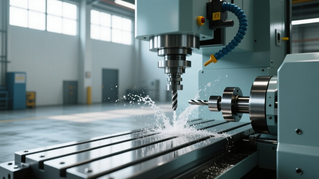
Modern CNC milling machine operation relies heavily on high-pressure TSC (typically 300 to 1,000 PSI) to evacuate chips from deep pockets and deep-hole drilling operations. A drop in TSC pressure leads to chip welding, tool breakage, and scrapped parts.
Troubleshooting the 1000 PSI Pump System
When the control throws a low-pressure TSC alarm, the issue is rarely the pump motor itself. Follow this diagnostic tree:
- Check the Vortex Filter: Located on the side of the coolant tank, the vortex separator removes fines down to 25 microns. If the underflow port (where the heavy chips exit) is clogged, the filter media blinds off, starving the high-pressure pump.
- Inspect the Pump Inlet Screen: The piston pump requires pristine fluid. A 100-mesh inlet screen protects the ceramic pistons. If operators use tramp-oil-heavy or degraded coolant, this screen clogs, causing cavitation. Cavitation destroys the pump's swashplate in under 50 operating hours.
- Verify the Rotary Union: The spindle rotary union transfers the high-pressure fluid from the stationary plumbing to the rotating spindle. If the union's carbon seals wear, you will see coolant leaking from the weep holes at the top of the spindle head. Replacement seals cost roughly $150, but ignoring the leak will allow coolant to ingress into the spindle bearings, causing catastrophic rust and failure.
Optimizing Nozzle Geometry for Evacuation
Pressure at the pump does not equal pressure at the cutting edge. According to Sandvik Coromant milling guidelines, coolant velocity is just as critical as pressure. Ensure your toolholders feature precision-ground coolant channels rather than drilled cross-holes. A restricted coolant channel in a cheap toolholder can drop the effective cutting-zone pressure by up to 60%, rendering the 1000 PSI pump useless for chip evacuation.
Advanced Geometric Verification: Ballbar Testing
If CNC milling machine operation yields parts with out-of-round bores or mismatched quadrant transitions, the machine's geometric alignment is compromised. While laser interferometry is the gold standard for linear accuracy, a telescoping ballbar (such as the Renishaw QC20 ballbar system) is the most practical tool for shop-floor diagnostics.
A ballbar test takes 15 minutes and maps servo mismatch, stick-slip, backlash, and squareness errors simultaneously. If the polar plot shows a distinct 'cloverleaf' pattern, the axis servos are poorly tuned for circular interpolation. This is corrected by adjusting the velocity loop gains (Parameter 2021 in Fanuc) to balance the X and Y axis response times. For comprehensive maintenance schedules and parameter backups, always refer to the OEM's official Haas Automation Service Tips or your specific control manufacturer's maintenance manual.
Mastering these diagnostic protocols transforms CNC milling machine operation from a reactive firefighting exercise into a predictable, high-precision manufacturing process. By systematically isolating servo lag, monitoring spindle retention force, and maintaining high-pressure coolant integrity, shops can eliminate phantom downtime and maintain tight tolerances across multi-day production runs.