Inside a Milling Machine with CNC: Technical Specs and Kinematics
Explore the technical specifications, drive mechanics, and controller architecture of a modern milling machine with CNC for precision manufacturing.
The Electromechanical Architecture of Modern CNC Mills
Understanding the internal architecture of a milling machine with CNC requires moving beyond basic G-code programming and examining the physical kinematics, drive systems, and feedback loops that dictate micron-level accuracy. A modern vertical or horizontal machining center is a closed-loop electromechanical system where digital interpolation meets high-torque servomechanics. In 2026, the gap between standard production mills and high-precision 5-axis machines is defined by thermal stability, direct-drive kinematics, and nanometer-scale controller resolution.
Kinematic Drive Systems: Ballscrews vs. Linear Motors
The translation of rotary servo motor output into linear axis movement is the foundation of CNC positioning. While traditional machines rely on ball screw assemblies, high-speed and high-precision mills increasingly utilize linear motor technology.
Precision Ball Screw Assemblies
Standard production mills, such as the widely deployed Haas VF series, utilize C3 or C5 grade precision ball screws. A C3 grade ball screw guarantees an accuracy of 8 microns over 300mm of travel. To eliminate axial backlash, these systems employ preloaded double-nut assemblies. The thrust bearings at the motor mount are typically ABEC-7 or ABEC-9 angular contact bearings, preloaded to withstand the high axial forces generated during rapid traverses and heavy roughing cuts.
Direct-Drive Linear Motors
For high-speed contouring and hard milling, linear motors remove the mechanical transmission entirely. By coupling the forcer directly to the moving mass, linear motors eliminate backlash, wind-up, and mechanical hysteresis. This allows for accelerations exceeding 1.5G (compared to the 0.5G typical of ball screws) and significantly reduces the following error during complex 3D surface milling.
| Specification | Precision Ball Screw (C3 Grade) | Direct-Drive Linear Motor |
|---|---|---|
| Max Acceleration | 0.3G - 0.5G | 1.0G - 2.0G |
| Backlash | 2-5 microns (requires compensation) | Zero (direct coupling) |
| Maintenance Cycle | Relubrication every 500-1000 hours | Virtually maintenance-free |
| Thermal Growth | Moderate (friction heat requires cooling) | High (requires active stator cooling) |
| Relative Cost Premium | Baseline | +35% to +50% per axis |
Spindle Architecture and Toolholding Interfaces
The spindle is the primary dynamic component of any milling operation. Modern spindles are categorized by their drive mechanism (belt, direct-drive, or motorized) and their toolholding taper.
Taper Interfaces: CAT40 vs. HSK-A63
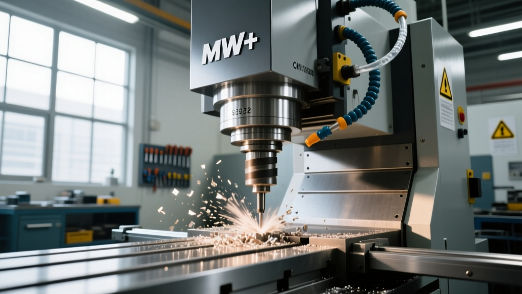
For spindles operating below 12,000 RPM, the CAT40 (V-flange) or BT40 taper remains the industry standard due to its high rigidity and tooling availability. However, as spindle speeds exceed 15,000 RPM, centrifugal force causes the spindle nose to expand radially. This expansion breaks the taper seal on a CAT40 holder, leading to tool pull-out and catastrophic chatter.
To solve this, high-speed mills utilize the HSK (Hohl Schaft Kegel) interface. The HSK-A63 taper features a 1:10 taper ratio and a simultaneous face-and-taper contact design. As centrifugal force increases, the hollow shank expands outward against the spindle face, actually increasing the clamping rigidity at high RPMs.
Expert Specification Note: When spec'ing a high-speed spindle, verify the bearing composition. Premium spindles utilize hybrid ceramic bearings featuring Silicon Nitride (Si3N4) balls. These ceramic balls are 40% lighter than steel, reducing centrifugal loading on the outer race at 20,000+ RPM, and possess a lower coefficient of thermal expansion, maintaining preload accuracy as temperatures rise.Controller Architecture and the Feedback Loop
The CNC controller (e.g., Fanuc 0i-F Plus, Siemens Sinumerik ONE, or Heidenhain TNC7) acts as the central nervous system. It does not merely send voltage to the servos; it manages a continuous, high-frequency closed-loop feedback cycle.
- Interpolation: The controller calculates the exact path, breaking down complex NURBS or G-code arcs into micro-segments, often utilizing nanometer-level internal resolution.
- Servo Command: A velocity/torque command is sent to the servo drive, which powers the motor.
- Motor Feedback (Inner Loop): A rotary encoder on the servo motor shaft reports position back to the drive at frequencies up to 4 kHz, ensuring the motor spins at the exact commanded velocity.
- Scale Feedback (Outer Loop): To account for ball screw thermal expansion or mechanical compliance, a linear glass scale mounted directly to the machine casting reports the actual table position. High-end enclosed linear encoders resolve positions down to 10 nanometers, allowing the controller to instantly correct any deviation between the commanded position and the physical axis location.
Look-Ahead and Jerk Control
When machining complex 3D aerospace contours, the controller must process thousands of tiny linear segments (G1 moves). Advanced controllers feature 'Look-Ahead' algorithms that scan up to 2,000 blocks ahead of the current execution point. This allows the system to anticipate sharp directional changes and decelerate smoothly, preventing dwell marks on the workpiece surface. Furthermore, modern 'Jerk Control' (the rate of change of acceleration) algorithms limit sudden spikes in motor torque, preserving surface finish and extending mechanical life.
Real-World Specifications: Production VMC vs. 5-Axis Precision
To contextualize these technologies, we can compare the technical specifications of a standard high-speed production mill against a premium 5-axis simultaneous machining center.
| Feature | Production VMC (e.g., Haas VF-2SS) | 5-Axis Precision (e.g., DMG MORI DMU 50 3rd Gen) |
|---|---|---|
| Base Construction | Meehanite Cast Iron | Polymer Concrete / Mineral Cast |
| Axis Drive | Direct-Speed Belt / Ballscrew | Torque Motors (Rotary) / Linear (X/Y) |
| Spindle Interface | CAT40 (12,000 RPM) | HSK-A63 (20,000 RPM) |
| Positioning Accuracy (VDI/DGQ) | ± 5.0 microns | ± 2.0 microns |
| Rapid Traverses (X/Y/Z) | 35.6 m/min | 60.0 m/min (Linear Motors) |
| Thermal Compensation | Spindle Chiller Only | Full Geometric & Ballscrew Cooling |
| Estimated Base Price (USD) | $85,000 - $110,000 | $350,000 - $480,000 |
Thermal Stability and Geometric Accuracy
The most critical, yet frequently overlooked, specification of a milling machine with CNC is thermal stability. As ballscrews rotate and spindles cut, friction generates heat. A standard steel ballscrew expands by approximately 12 microns per meter for every 1°C rise in temperature. In a high-production environment, a 1-meter Y-axis ballscrew can easily experience a 5°C temperature gradient, resulting in 60 microns of positional drift—enough to scrap tight-tolerance aerospace components.
To combat this, premium machines utilize core-cooled ballscrews, where chilled fluid is pumped directly through the hollow center of the screw shaft, maintaining a constant 20°C (± 0.1°C). Additionally, the machine base material plays a vital role. While Meehanite cast iron offers excellent dampening for heavy roughing, high-precision 5-axis mills increasingly utilize polymer concrete (mineral cast) bases. Polymer concrete possesses a thermal inertia up to six times greater than cast iron and a vibration dampening factor that is three to five times higher, ensuring that ambient shop temperature fluctuations do not distort the machine's geometric alignment.