
Mastering the CNC Mill Machine: Operator Training Best Practices
Master the CNC mill machine with expert operator training protocols. Learn pre-flight checks, tooling torque specs, and first-part execution strategies.
Operator Training Objective
Transitioning from a basic button-pusher to a master machinist requires a rigorous understanding of machine dynamics, tooling physics, and systematic verification. This guide outlines the exact protocols required to operate a modern CNC mill machine safely and efficiently, minimizing scrap rates and preventing catastrophic spindle crashes.
The Pre-Shift Machine Audit and Thermal Stabilization
Before loading a single piece of stock, a trained operator must verify the mechanical and thermal baseline of the CNC mill machine. Skipping this step is the leading cause of Z-axis dimensional drift during the first hour of production.
Fluid and Pressure Verification
- Way Lube System: Verify the reservoir is filled with the correct ISO 68 way oil (e.g., Mobil Vactra No. 2). Check the pressure switch cycle; on most vertical machining centers (VMCs), the pump should cycle every 15 to 20 minutes, building to 15-20 PSI before dropping off. A continuously running pump indicates a broken line or a failed metering valve.
- Spindle Chiller: Check the chiller unit's temperature delta. The coolant must be maintained within ±1°C of the ambient shop temperature. If the shop is 68°F (20°C) and the chiller is set to 60°F, the spindle will contract, causing the Z-axis to cut short by up to 0.0015 inches over a 4-hour cycle.
- Coolant Concentration: Use a refractometer to check the cutting fluid. For semi-synthetic coolants like Master Fluid Solutions TRIM MicroSol 585XT, maintain a 6% to 8% concentration. Multiply the refractometer reading by the fluid's specific multiplier (usually 1.0 to 1.5) to get the true percentage. Running below 5% invites flash rust and bacterial growth.
Spindle Warm-Up Protocol
Never start heavy roughing on a cold spindle. Bearings require time to reach thermal equilibrium and distribute grease evenly. Execute a stepped warm-up program:
- Run at 1,500 RPM for 5 minutes.
- Step up to 4,000 RPM for 5 minutes.
- Step up to 80% of the machine's maximum RPM (e.g., 9,600 RPM on a 12k spindle) for 5 minutes.
Expert Insight: If your CNC mill machine is equipped with a spindle growth compensation sensor, verify the probe is clean and reading correctly. A dirty sensor will feed false thermal expansion data to the control, ruining tight-tolerance bore depths.
Tooling Setup: Avoiding the $15,000 Pull-Out Crash
Tool retention is a critical safety and precision variable. The most common cause of a tool pulling out of the spindle during a heavy cut is an improperly torqued retention knob (pull stud) or a mismatched knob angle.
Retention Knob Torque Specifications
Using a standard impact wrench or overtightening with a breaker bar stretches the retention knob, causing it to bottom out in the spindle drawbar. This prevents the tool taper from fully seating, resulting in severe TIR (Total Indicator Runout) and eventual tool ejection.
| Toolholder Taper | Retention Knob Style | Recommended Torque (ft-lbs) | Common Failure Mode if Over-Torqued |
|---|---|---|---|
| CAT40 | 45-Degree (e.g., Haas, Fadal) | 25 - 35 ft-lbs | Taper bulge, poor seating, high TIR |
| CAT40 | 90-Degree (e.g., Mazak, Mori Seiki) | 30 - 40 ft-lbs | Drawbar thread stripping, tool drop |
| BT40 | MAS-P 45-Degree | 20 - 30 ft-lbs | Spindle nose damage, vibration |
| HSK-A63 | Hollow Shank (Clamping) | N/A (Internal retention) | Collet spring fatigue if forced |
Always use a calibrated torque wrench specifically designed for retention knobs, such as those from Maritool or Techniks. For deeper technical specifications on toolholder clamping forces and taper interfaces, refer to the Sandvik Coromant milling knowledge base.
The 'First Part' Execution Methodology
Pressing 'Cycle Start' on a new program requires a systematic verification process. Relying solely on the machine's graphical simulation is insufficient, as simulations rarely account for actual tool stick-out, vise jaw clearances, or incorrect work offsets.
The Single-Block and Distance-to-Go (DTG) Protocol
For the first run of any CNC mill machine program, configure the control panel as follows:
- Rapid Override: Set to 5% or 25%.
- Feedrate Override: Set to 50%.
- Single Block: ON.
- Optional Stop (M01): ON (ensure the machine is configured to read M01).
Position your eyes on the Distance to Go (DTG) screen, not the Absolute or Machine coordinates. As the tool approaches the part, the Z-axis DTG should perfectly match the clearance height programmed in your CAM software. If the DTG reads 0.100" but the tool tip is physically touching the part, your Z-axis work offset (G54) is incorrect. Hit Feed Hold immediately.
Crash Prevention Rule
Never trust a G43 (Tool Length Compensation) value that was manually typed into the offset page. Always use a tool presetter or a spindle-mounted probe to automatically write the geometry offset. Manual data entry errors are responsible for over 40% of catastrophic Z-axis crashes.
Advanced Troubleshooting: Chatter and Tool Deflection
When a CNC mill machine produces a high-pitched squeal during peripheral milling, the operator must know how to adjust parameters to eliminate chatter without sacrificing cycle time.
Radial vs. Axial Engagement Adjustments
Chatter is a harmonic resonance between the tool and the workpiece. To break the harmonic frequency, alter the engagement:
- Reduce Radial Depth of Cut (RDOC): If you are slotting (100% RDOC) with a 1/2" end mill and experiencing chatter, reduce the stepover to 10% of the tool diameter (0.050").
- Increase Axial Depth of Cut (ADOC): To maintain the same material removal rate (MRR), increase the Z-depth. This utilizes the rigid shank of the tool rather than the flutes.
- Adjust Spindle Speed (RPM): Use a tap test or software like CutPro to find the machine's stable speed zones. Often, simply increasing or decreasing the RPM by 15% will move the cutting frequency out of the harmonic chatter zone.
For more on managing cutting forces and avoiding deflection, operators should review the troubleshooting guides available via the Haas Automation service tips portal, which provides excellent visual aids for identifying tool wear patterns.
Operator Safety and Machine Guarding
Operating a CNC mill machine involves high kinetic energy, sharp tooling, and high-pressure coolant. Safety is not just a corporate mandate; it is a critical operational discipline.
- Interlock Defeat: Never zip-tie or tape down door interlock switches. Bypassing safety interlocks exposes the operator to flying carbide fragments and high-velocity workpieces. The OSHA machine guarding standards strictly prohibit the defeat of primary safety enclosures, and violations carry severe financial and legal penalties.
- Chip Management: Never use compressed air to blow chips out of the enclosure while the spindle is rotating. Compressed air atomizes the coolant, creating a respirable mist that violates air quality standards and coats the machine's way covers, accelerating wear. Use a designated chip hook and brush during spindle stops only.
- Ergonomics: When loading heavy vises or tombstones, use the overhead crane or a pneumatic lift assist. A standard 6-inch Kurt-style milling vise weighs over 70 lbs; repetitive manual loading leads to severe lower back fatigue and compromised clamping consistency.
By adhering to these rigorous pre-flight, tooling, and execution protocols, operators transform the CNC mill machine from a simple automated cutter into a high-precision manufacturing instrument. Mastery lies in the details: the torque of a pull stud, the concentration of the coolant, and the vigilant monitoring of the distance-to-go screen.
Related reading

Reshaping Alternatives to Spindle: Practical, High-Precision Non-Spindle Machining Solutions for Modern CNC Shops
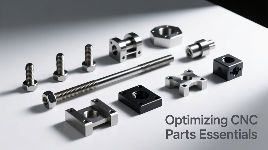
Optimizing CNC Parts Essentials: Precision, Efficiency, and Real-World Best Practices