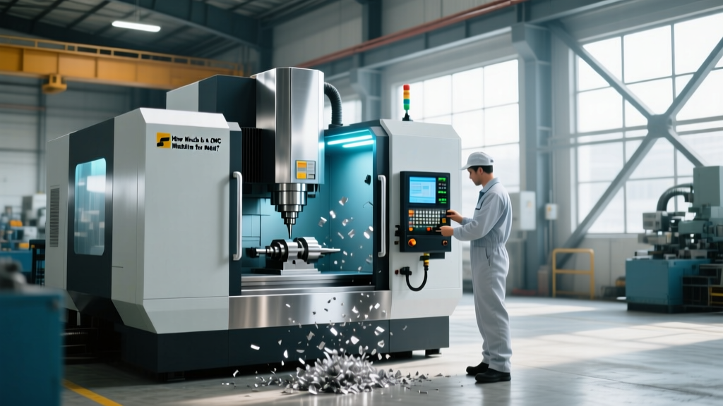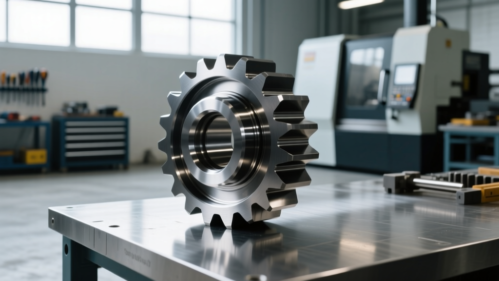
Troubleshooting Precision CNC Machined Carbon Steel Parts
Diagnose and fix surface defects, tool wear, and chatter when manufacturing precision CNC machined carbon steel parts like 1045 and 4140 alloys.
The Metallurgical Reality of Carbon Steel Machining
Manufacturing precision CNC machined carbon steel parts requires navigating a narrow window of optimal cutting parameters. Medium-carbon steels like AISI 1045 and low-alloy variants like AISI 4140 dominate the industrial sector due to their tensile strength and cost-efficiency. However, their specific metallurgical profiles—particularly carbon content ranging from 0.42% to 0.50% in 1045, and the addition of chromium and molybdenum in 4140—create distinct failure modes during CNC turning and milling.
When tolerances tighten to ISO 286 H7 (±0.015mm for a 50mm diameter), standard machining heuristics fail. Surface finish degradation, harmonic chatter, and accelerated insert wear are not random anomalies; they are direct symptoms of improper thermal management, incorrect tool geometry, or harmonic resonance. This guide provides a rigorous troubleshooting framework for resolving the most common defects encountered when machining precision carbon steel components.
CRITICAL WARNING: Never attempt to machine pre-hardened 4140 steel (28-32 HRC) with standard uncoated or PVD-coated carbide inserts. The extreme abrasiveness of the chromium carbides will cause catastrophic flank wear within 30 seconds of cut time. Always specify CVD-coated Al2O3/TiCN inserts (e.g., Sandvik GC4225 or Kennametal KCP25) for pre-hardened alloy steels.Diagnostic Matrix: Surface Defects and Tool Wear
Identifying the root cause of a defect requires analyzing the physical evidence left on the workpiece and the cutting tool. Use the following diagnostic matrix to isolate the failure mode.
| Symptom | Visual Indicator | Root Cause | Immediate Parameter Fix |
|---|---|---|---|
| Built-Up Edge (BUE) | Material welded to insert rake face; torn surface finish | Cutting speed too low; high chemical affinity at 400°C-600°C | Increase Vc to >220 m/min; switch to sharp PVD TiAlN coating |
| Depth-of-Cut Notching | V-shaped groove at the DOC line on the insert edge | Work-hardened scale or previous cut boundary; oxidation | Employ wiper geometry; vary DOC by 0.5mm per pass |
| Harmonic Chatter | Equally spaced, high-frequency wave marks on the OD | Tool overhang exceeds 4x diameter; RPM matches natural frequency | Reduce RPM by 15%; switch to anti-vibration damped boring bar |
| Crater Wear | Concave depression on the insert rake face behind the edge | Excessive thermal load causing chemical diffusion | Reduce feed rate (fn) by 20%; increase high-pressure coolant to 1000 psi |
Troubleshooting Built-Up Edge (BUE) on 1045 Steel
AISI 1045 is notorious for Built-Up Edge (BUE) formation during finishing operations. BUE occurs when the localized temperature at the shear zone reaches the plasticization point of the carbon steel (typically between 400°C and 600°C), causing microscopic particles of the workpiece to weld onto the cutting edge. As the BUE grows and eventually breaks off, it tears the workpiece surface, resulting in an Ra (roughness average) exceeding 3.2 µm—unacceptable for precision CNC machined carbon steel parts requiring tight seal interfaces.
The Speed and Geometry Solution
To eliminate BUE, you must push the cutting temperature past the adhesion threshold. According to Sandvik Coromant's steel machining guidelines, increasing the cutting speed (Vc) above 220 m/min (approx. 720 SFM) transitions the chip formation into a stable, continuous flow that carries heat away from the shear zone.
If your machine spindle lacks the RPM to achieve this surface speed on larger diameters, you must alter the tool geometry. Switch from a standard CVD-coated insert to a highly polished, sharp-edged PVD TiAlN insert. The PVD coating process operates at lower temperatures, preserving a sharper cutting edge (edge radius < 10 µm) that shears the 1045 steel cleanly rather than plowing through it.
Eliminating Chatter in High-L/D Ratio 4140 Shafts
When turning long, slender 4140 chromoly shafts (Length-to-Diameter ratio > 8:1), harmonic chatter is the primary barrier to holding cylindrical tolerances. Chatter is a self-excited vibration caused by the regenerative effect of the tool passing over previously machined waviness.
'Chatter in carbon steel turning is rarely a rigidity issue with the machine base; it is almost always a localized resonance issue at the tool-workpiece interface.' — Kennametal Tooling Knowledge Base
Implementing Damped Tooling and RPM Tuning
Standard solid carbide or steel boring bars will deflect and vibrate at overhangs beyond 4x their diameter. For precision internal machining of 4140 parts, you must deploy heavy-metal or damped anti-vibration toolholders (such as Sandvik Silent Tools or Kennametal KenTIP). These tools contain internal tuned mass dampers that absorb vibrational energy.
Furthermore, you must tune the spindle RPM. Conduct a 'tap test' using an accelerometer to identify the natural frequency of your specific tool assembly. Once identified, use a stability lobe diagram to select an RPM that places the tooth-pass frequency in a stable zone. In many cases, simply dropping the spindle speed by 12% to 18% will move the operation out of the resonant peak, instantly eliminating chatter marks and saving a $350 workpiece from the scrap bin.
Thermal Management and Dimensional Drift
Precision CNC machined carbon steel parts are highly susceptible to thermal expansion. The coefficient of thermal expansion (CTE) for AISI 1045 is approximately 11.2 µm/m·°C. While this seems negligible, consider a 600mm long drive shaft machined to an H7 tolerance. If the localized cutting heat and ambient shop temperature cause the part to rise by just 12°C (from a baseline 20°C to 32°C), the shaft will expand by 0.080mm. When the part cools to room temperature for CMM inspection, it will measure 0.080mm undersized, failing the tolerance check.
Thermal Control Protocol:- Maintain CNC coolant temperature strictly at 20°C (68°F) using a chiller unit.
- Run a 15-minute warm-up cycle on the spindle and axes to stabilize machine geometry before cutting precision bores.
- Use flood coolant at a minimum concentration of 8% to ensure adequate heat transfer; lean mixtures (below 5%) lack the specific heat capacity to pull thermal energy out of the 4140 workpiece.
Step-by-Step Resolution for Poor Surface Finish (Ra > 1.6 µm)
When a finishing pass on a carbon steel component fails to achieve the required 1.6 µm (63 µin) surface finish, follow this sequential troubleshooting protocol before scrapping the tooling.
- Verify Insert Nose Radius (rε): Surface finish is mathematically tied to feed rate and nose radius. Use the formula Ra = fn² / (32 * rε). If you are feeding at 0.20 mm/rev with a 0.4mm nose radius, your theoretical Ra is 3.1 µm. Increase the nose radius to 0.8mm or drop the feed to 0.12 mm/rev.
- Inspect for Micro-Chipping: Use a 20x loupe to inspect the insert edge. Carbon steel inclusions (like manganese sulfides) can cause micro-chipping on standard grades. If chipping is present, switch to a tougher substrate grade (e.g., from a P20 to a P30 ISO classification).
- Adjust Coolant Delivery: Ensure the coolant nozzle is aimed precisely at the shear zone, not just flooding the general area. For finishing, high-pressure coolant (minimum 70 bar / 1000 psi) is required to mechanically break the chip and prevent it from scratching the newly machined surface.
- Check Wiper Engagement: If using wiper inserts, verify that the feed rate is exactly matched to the wiper geometry. Feeding too slow allows the wiper flat to rub against the carbon steel, causing work-hardening and a smeared, glossy (but dimensionally inaccurate) surface.
Tooling Economics: Cost vs. Lifecycle in Carbon Steel
Shop managers often default to the cheapest carbide inserts to reduce upfront costs. However, when producing precision CNC machined carbon steel parts, this approach destroys profitability through downtime and scrap. A standard economy CNMG 432 insert may cost $6.00, but it will require indexing every 45 minutes when machining abrasive 4140. A premium, multi-layer CVD-coated insert (like the Sandvik GC4225) costs between $14.00 and $18.00 per edge, but will reliably machine for 140+ minutes. The 3x increase in edge life reduces non-cutting time (indexing and tool setting) by 65%, yielding a net cost-per-part reduction of roughly 22% in high-volume production environments.
Frequently Asked Questions
Can I use CBN (Cubic Boron Nitride) inserts for all carbon steel parts?
No. CBN is strictly reserved for hardened carbon steels (typically > 45 HRC). Using CBN on soft or pre-hardened 1045/4140 (under 32 HRC) will result in rapid chemical wear and catastrophic edge failure, as the iron in the soft steel chemically reacts with the boron at high cutting temperatures. Reserve CBN for hardened gears and bearing races.
Why is my 1045 steel producing long, stringy chips that tangle in the toolholder?
AISI 1045 lacks the sulfur or lead additives found in free-machining steels (like 12L14), meaning it naturally forms continuous, ductile chips. To break these chips, you must increase the feed rate (fn) to thicken the chip, forcing it to curl tighter and snap against the workpiece. Alternatively, specify inserts with aggressive chipbreaker geometries designed specifically for medium-carbon steels (e.g., ISO 'PM' or 'M' chipbreakers).
What is the best coolant strategy for deep-hole drilling in 4140?
Standard flood coolant is insufficient for deep-hole drilling (L/D > 5) in 4140 due to poor chip evacuation. You must use through-tool coolant at a minimum of 150 bar (2100 psi). This high-pressure stream fractures the chip at the cutting edge and forces it out of the flutes, preventing the chip from re-welding to the bore wall and ruining the concentricity of the precision part.
For further metallurgical data on carbon steel classifications and their impact on machinability, consult the ASM International Materials Resource Hub.