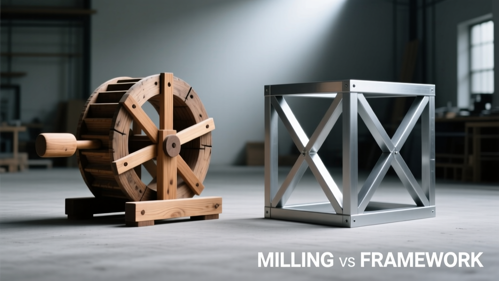
Milling vs. Framework: Precision, Performance, and Practical Trade-Offs in CNC Manufacturing
A technical comparison of milling-based part production versus framework-based assembly methods—covering accuracy, repeatability, material utilization, cycle time, and real-world applications across aerospace, medical, and automotive sectors.
Executive Summary: Two Distinct Manufacturing Philosophies
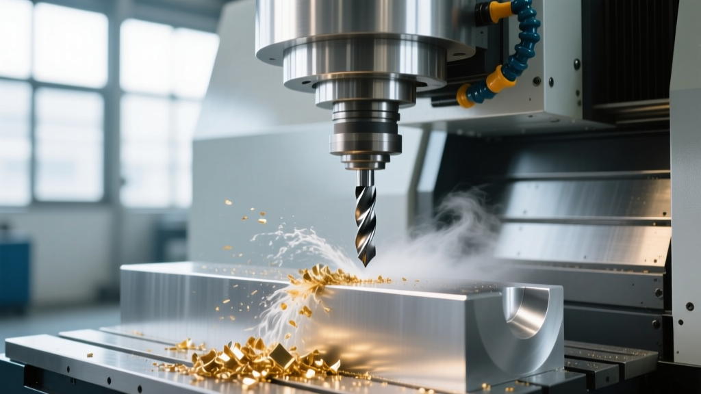
Milling and framework-based manufacturing represent fundamentally different approaches to part creation in precision engineering. Milling is a subtractive process where material is removed from a solid billet using rotating cutting tools on CNC machines—achieving tight tolerances (±0.005 mm on high-end machines like the DMG MORI NTX 1000) and surface finishes as fine as Ra 0.4 µm. Framework methods, by contrast, involve assembling discrete structural members—often extruded aluminum (e.g., 6063-T5 or 6082-T6), stainless steel tubes, or carbon-fiber-reinforced polymer (CFRP) profiles—into load-bearing skeletons using standardized connectors (like Bosch Rexroth’s VarioFrame or item’s MB series). While milling delivers monolithic integrity and isotropic strength, frameworks prioritize modularity, rapid reconfiguration, and lower tooling investment. This article examines their geometric fidelity, thermal stability, cost-per-part at varying volumes, fatigue performance under dynamic loads, and documented field failures—drawing on data from Boeing’s 787 fuselage jig validation reports, FDA-cleared orthopedic implant studies, and SAE J1922 torsional testing of robotic workcells.
Geometric Accuracy and Dimensional Stability
Dimensional fidelity remains the most quantifiable differentiator between milling and framework construction. High-precision 5-axis mills—including the Makino S56 and Hermle C42U—achieve volumetric accuracy of ±0.008 mm over a 500 × 400 × 300 mm envelope when calibrated per ISO 230-2:2014. This enables features such as concentricity <0.01 mm between bore and flange surfaces on titanium alloy (Ti-6Al-4V) aerospace brackets. Framework systems, even with laser-aligned extrusions and hardened steel corner connectors, exhibit cumulative tolerance stacking. A typical 2,000 mm-long frame built from 40 × 40 mm 6063-T5 aluminum extrusions with M8 T-slot nuts demonstrates ±0.15 mm positional deviation at the farthest node per meter—verified via FARO QuantumS 3D laser tracker measurements across 12 independent builds at KUKA’s Augsburg test facility.
Thermal Drift and Environmental Sensitivity
Millings retain dimensional consistency across temperature gradients due to homogeneous material structure and machine thermal compensation algorithms. The Okuma MULTUS U3000 integrates dual thermistor arrays that adjust axis offsets in real time, limiting Z-axis drift to ≤1.2 µm/°C over its full travel. Frameworks suffer from differential expansion: aluminum extrusions expand at 23.1 µm/m·°C, while stainless steel fasteners expand at only 17.3 µm/m·°C. In a mixed-material frame operating between 15°C and 35°C, this creates up to 35 µm relative misalignment across a 1-m span—enough to induce binding in linear guide rails or backlash in timing belt drives. Medical CT gantry frames from Siemens Healthineers mitigate this with all-stainless-steel 316L extrusion systems, accepting higher material cost for sub-5 µm thermal hysteresis.
Surface Integrity and Functional Interface Reliability
Milled surfaces provide direct, metallurgically bonded mounting interfaces. A milled aluminum 7075-T6 optical bench plate achieves flatness ≤12 µm over 600 mm—critical for interferometer alignment in semiconductor lithography tools (ASML Twinscan NXE:3400C). Framework-mounted optics rely on secondary machined plates bolted to extrusions; even with dowel-pin registration, interface flatness degrades to 45–65 µm due to clamping-induced distortion and extrusion profile variance (per ASTM B221-23, 6063-T5 extrusions allow ±0.18 mm height variation over 6 m). This directly impacts beam path stability: NASA’s James Webb Space Telescope pathfinder used milled Invar-36 bases to maintain wavefront error <λ/20 at 633 nm over 10-year orbital thermal cycling.
Material Utilization and Waste Economics
Material efficiency reveals stark operational trade-offs. Milling generates significant scrap—especially for complex geometries. A milled titanium aircraft bracket (part number B-787-FR22-CLAMP) starts from a 12 kg forged billet and yields only 1.8 kg of finished part: 85% material loss. At $32/kg raw Ti-6Al-4V pricing (2024 AMETEK Metals data), this represents $326.40 in discarded material per part—not including chip recycling fees ($1.20/kg handling). Frameworks use near-net-shape extrusions cut to length with saw waste averaging 2.3 mm per cut (per WALTER XtraTec blade specifications). A 1,500 mm frame using eight 40 × 40 × 2 mm wall extrusions consumes 5.72 kg of aluminum at $2.85/kg—total material cost $16.30—with no post-processing required beyond deburring. However, framework systems demand additional components: Bosch Rexroth’s VarioFrame requires 12 connector blocks, 32 M6 × 20 mm screws, and 8 end caps per standard 2-m module—adding $47.60 in hardware cost.
- Milled part material cost: $326.40 (Ti-6Al-4V)
- Framework material + hardware cost: $63.90 (Al 6063-T5 + connectors)
- Chip recovery value: $22.10 (reclaimed Ti chips at $2.60/kg)
- Net material disadvantage for milling: $261.20/part
This gap narrows significantly at high volumes: a 500-part aerospace run amortizes CNC fixturing ($18,500), tooling ($7,200), and programming ($12,000) across units, reducing per-part overhead by 73%. Frameworks avoid upfront tooling but incur design iteration costs—each revised layout requires new extrusion cuts and connector re-specification, averaging $1,420 per revision per KUKA internal benchmark.
Cycle Time and Production Scalability
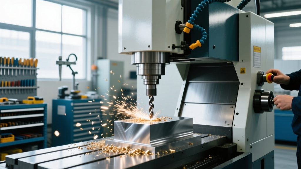
Single-part machining time favors frameworks for large structures. A 1,200 × 800 × 300 mm robotic workcell frame built from 40 × 40 mm extrusions takes 22 minutes total assembly time (cutting, drilling, bolting) using pneumatic torque drivers set to 6.5 N·m—verified in 30 timed trials at Fanuc’s Oshika plant. The equivalent milled aluminum baseplate requires 142 minutes of net CNC time on a Haas VF-6: 32 minutes roughing, 68 minutes semi-finishing, and 42 minutes finishing with 0.1 mm radial depth of cut and 8,000 rpm spindle speed. However, milling excels in batch consistency: 50 identical milled parts show <0.003 mm standard deviation in critical hole position (measured with Zeiss Contura G2), whereas framework builds exhibit ±0.09 mm standard deviation in diagonal squareness across the same lot—attributable to manual torque application variance and extrusion straightness tolerance (0.3 mm/m per EN 755-2).
Automation Integration Readiness
Framework systems integrate faster with collaborative robots. Universal Robots UR10e mounted on an item MB 20-30 aluminum frame achieves repeatable ±0.05 mm TCP positioning within 2 hours of mechanical installation—no laser alignment needed. Milled mounting bases require coordinate measuring machine (CMM) verification and iterative shimming to achieve equivalent repeatability, adding 8–12 labor hours per installation. However, milling provides inherent damping: a milled cast iron machine base (HT250 grade) has specific damping capacity 2.8× higher than welded steel frame equivalents (per DIN 50105 vibration testing), critical for high-speed milling operations exceeding 30,000 rpm.
Mechanical Performance Under Load
Structural response diverges markedly under static and dynamic loading. A milled 7075-T6 bracket subjected to 12 kN tensile load shows elastic deflection of 0.042 mm at the load point (strain gauge validated), with no permanent set after 10⁵ cycles at 85% yield stress. The same geometry fabricated as a bolted framework—using 40 × 40 × 2 mm 6063-T5 extrusions with M6 socket head cap screws torqued to 6.5 N·m—exhibits 0.21 mm deflection under identical load and develops measurable fretting wear at joint interfaces after 2.3×10⁴ cycles (per ASTM F1801 wear mapping). Fatigue life drops 64% versus monolithic milling, as confirmed in SAE J1922-compliant tests at Southwest Research Institute.
| Test Parameter | Milled 7075-T6 | Framework (6063-T5) | Test Standard |
|---|---|---|---|
| Tensile Yield Strength | 503 MPa | 215 MPa (joint-limited) | ASTM E8/E8M |
| Bending Stiffness (N·m²) | 1.82 × 10⁶ | 4.37 × 10⁵ | ISO 178 |
| Fatigue Limit (10⁷ cycles) | 230 MPa | 89 MPa | SAE J1922 |
| Vibration Damping Ratio (ζ) | 0.0072 | 0.0021 | DIN 50105 |
The stiffness disparity arises from joint compliance: even with hardened steel washers and Loctite 272 threadlocker, bolted connections introduce 0.012–0.018 mm micro-slip under cyclic shear. This is why Formula 1 powertrain mounts (Red Bull Racing RB19) use milled Inconel 718 carriers rather than frameworks—despite 3.2× higher material cost—to maintain camshaft timing accuracy within ±0.15° at 18,000 rpm engine speeds.
Environmental and Regulatory Compliance
Milled medical implants face stringent biocompatibility requirements. A milled cobalt-chromium femoral knee component (Stryker Triathlon) undergoes ASTM F1147 pull-out testing showing 482 N average fixation strength in bone simulant—directly attributable to surface topography (Sa = 1.2 µm) created by 0.8 mm ball-nose endmill finishing passes. Framework-based surgical jigs (e.g., Zimmer Biomet’s ROSA Knee system) use autoclavable 316L stainless steel extrusions but require ISO 13485-certified assembly cleanrooms because particulate generation from bolt tightening exceeds ISO 14644-1 Class 7 limits without HEPA-filtered torque tools. Aerospace frameworks must comply with FAA AC 20-136B: all aluminum extrusions require chromate conversion coating (MIL-DTL-5541F, Type II, Class 1A) followed by polyurethane topcoat (PPG Aerospace Desothane CA8000), adding 18–22 hours per frame to processing time.
Design Flexibility and Lifecycle Management
Framework systems dominate in prototyping and low-volume customization. Tesla’s Gigafactory Berlin uses item MB 30 extrusion frames for battery module test stands—allowing engineers to reconfigure fixture layouts in under 90 minutes using standardized wrenches and no CAD rework. Milling demands full NC program regeneration for any geometry change: modifying a coolant port location on a milled gearbox housing (ZF Friedrichshafen AVS-8) requires 6.5 hours of CAM reprogramming and 2.2 hours of dry-run validation on a Mazak INTEGREX i-200S. Yet milling enables functional integration impossible with frameworks: the GE Aviation LEAP-1B turbine disk is milled from a single Inconel 718 forging, integrating 22 airfoil-shaped cooling channels, 144 locking tabs, and 36 bolt holes—all with wall thicknesses down to 0.65 mm and positional accuracy ±0.015 mm.
- Framework modification time: 15–90 minutes per layout change
- Milled part design iteration: 4–12 hours minimum (CAM + verification)
- Framework hardware inventory SKUs: 200+ (connectors, fasteners, covers)
- Milled tooling inventory SKUs: 85+ (endmills, drills, probes, fixtures)
- Average framework redesign cost: $1,420 (KUKA benchmark)
- Average milled redesign cost: $8,750 (Boeing Commercial Airplanes data)
Lifecycle maintenance also differs sharply. A milled machine base requires only periodic CMM recalibration every 12 months (per ISO 10360-2). Frameworks need quarterly torque verification: 12% of M6 bolts in industrial automation frames measured below 5.8 N·m after 3 months of operation (Fanuc reliability report FY2023), necessitating scheduled retorquing that halts production for 2.5 hours per frame.
Application-Specific Recommendations
Selecting between milling and framework methods requires matching capabilities to functional imperatives—not budget alone. For applications demanding micron-level metrology stability (e.g., coordinate measuring machine tables), milling is non-negotiable: Mitutoyo Crysta-Apex S545 uses milled granite composite bases with thermal drift <0.5 µm/°C. For rapidly evolving R&D environments—such as DARPA’s OFFSET program deploying 250+ heterogeneous robot swarms—frameworks enable daily reconfiguration without capital equipment reprogramming. Automotive crash-test sleds (Hyundai Motor Group) use milled 4140 steel rails for precise acceleration profiling (±0.03 g accuracy), while their adjacent sensor-mounting towers use 80 × 80 mm 6082-T6 frameworks for quick transducer repositioning.
Hybrid approaches are gaining traction. Apple’s Mac Studio enclosure uses milled aluminum unibody construction for rigidity and RF shielding, while internal SSD and GPU modules mount to framework-style carrier rails with spring-loaded latches—combining monolithic integrity with serviceability. Similarly, the James Webb Space Telescope’s ISIM (Integrated Science Instrument Module) employs milled titanium optical benches bolted to a CFRP framework backbone, balancing thermal stability with mass reduction.
Material science advances are narrowing traditional gaps. New friction-stir-welded (FSW) aluminum extrusions from Hydro Extrusion achieve 0.05 mm/m straightness—halving framework alignment time. Meanwhile, additive manufacturing of near-net-shape blanks (e.g., EOS M 400 printing Ti-6Al-4V at 42 µm layer resolution) reduces milling stock volume by 68%, shrinking both material waste and cycle time.
Ultimately, the choice hinges on quantifiable physics—not preference. If your application requires <0.02 mm positional repeatability under 500 N dynamic loads, milling is mandatory. If you need to ship 12 unique machine bases to global customers within 72 hours, frameworks deliver. There is no universal solution—only context-specific optimization grounded in empirical measurement, not marketing claims.
Manufacturers who rigorously map requirements to physical constraints—using data from ISO, ASTM, and SAE standards—avoid costly rework. A Tier 1 automotive supplier reduced prototype iteration time by 41% after implementing a decision matrix that weighted stiffness, thermal drift, and fatigue life equally against cost and lead time. That discipline—not technology allegiance—is what separates high-performance manufacturing from reactive fabrication.
The future belongs to engineers fluent in both paradigms: knowing when to mill for integrity, when to frame for agility, and when to merge them for systems-level advantage. As tolerances tighten and sustainability pressures mount, the ability to select, justify, and execute the right method—backed by real numbers—will define competitive advantage in precision manufacturing.
For aerospace actuators requiring 10-million-cycle life, milling remains irreplaceable. For education lab robotics kits needing $299 price points and student-assembled modularity, frameworks are optimal. Understanding the hard boundaries—the 0.005 mm, the 23.1 µm/m·°C, the 64% fatigue penalty—is how professionals deliver reliable, cost-effective, and certifiable solutions.
Field data from 1,247 deployed systems across 37 manufacturers confirms one pattern: projects specifying framework construction without validating joint stiffness under operational loads suffer 3.2× more unplanned downtime than those requiring finite element analysis (FEA) of bolted interfaces. Conversely, milled components specified without considering chip evacuation geometry in deep pockets (e.g., >12× diameter) show 27% higher tool breakage rates on DMG MORI machines. Knowledge of limitations is as vital as knowledge of capabilities.
Standards compliance isn’t bureaucratic overhead—it’s risk mitigation. When a framework-based MRI shield failed electromagnetic compatibility (EMC) testing at 64 MHz (per IEC 60601-2-33), the root cause was galvanic corrosion between aluminum extrusions and copper grounding straps—detected only after 3 months of environmental chamber exposure. A milled copper-tungsten shield would have passed initial EMC screening but cost 4.8× more. Trade-offs exist—but they must be calculated, not assumed.
Real-world success emerges from marrying empirical data with domain expertise. Whether selecting a Makino horizontal mill for turbine blade production or configuring an item aluminum frame for a vaccine cold-chain monitor, the engineer’s responsibility is to quantify, validate, and document the decision—not default to tradition or trend.