Troubleshooting CNC Machine Aluminum Cutting: Fix Chatter and BUE
Fix built-up edge, chatter, and tool breakage during CNC machine aluminum cutting. Expert troubleshooting steps, speeds/feeds, and coating guides.
Diagnostic Matrix: Identifying Aluminum Machining Failures
CNC machine aluminum cutting presents unique tribological challenges. Unlike steel, aluminum alloys (specifically the 6xxx and 7xxx series) possess high ductility and a strong chemical affinity for the cobalt binders used in tungsten carbide tooling. This results in Built-Up Edge (BUE), harmonic chatter, and catastrophic tool failure if parameters are mismanaged. Use the diagnostic matrix below to identify your specific failure mode before adjusting parameters.
Symptom-to-Solution Flowchart
- Symptom: Shiny, welded material on the cutting edge; poor surface finish.
- Root Cause: BUE from incorrect tool coating, insufficient rake angle, or degraded coolant lubricity.
- Immediate Fix: Switch to TiB2 or ZrN coated tooling (or uncoated polished carbide), increase primary rake to 15°+, and verify coolant concentration.
- Symptom: High-pitched squeal, wavy surface finish, premature tool wear.
- Root Cause: Regenerative harmonic chatter due to excessive tool stickout or incorrect helix angle.
- Immediate Fix: Reduce stickout to under 3x diameter, switch to a 45° helix end mill, and alter spindle RPM by 10-15% to break the harmonic frequency.
- Symptom: Tool snaps at the shank intersection or flute packing occurs.
- Root Cause: Chip recutting and gullet overload.
- Immediate Fix: Drop from a 3-flute to a 2-flute end mill, increase compressed air blast, and verify chipload is generating thick enough chips to carry heat away.
Eradicating Built-Up Edge (BUE) and Material Welding
Built-Up Edge occurs when the workpiece material pressure-welds to the cutting edge of the tool. In CNC machine aluminum cutting operations, this is primarily driven by the chemical affinity between aluminum and the cobalt binder in standard carbide inserts and end mills. When BUE forms, it alters the effective geometry of the tool, increasing cutting forces and eventually tearing out chunks of the carbide substrate when the BUE breaks off.
Tool Coating and Geometry Selection
Never use Titanium Aluminum Nitride (TiAlN) coatings for aluminum. The aluminum in the coating creates a chemical bond with the aluminum workpiece, accelerating welding. Instead, specify the following tooling parameters:
- Titanium Diboride (TiB2): Extremely smooth, low-friction coating ideal for high-silicon aluminum alloys (e.g., A380 or 390).
- Zirconium Nitride (ZrN): Provides a hard, slick surface that resists material adhesion in standard 6061-T6.
- Uncoated Polished Carbide: For pure aluminum or highly gummy alloys, an uncoated micro-grain carbide with a mirror-polished flute surface often outperforms coated alternatives.
- Rake Angle: Demand a high positive primary rake angle (15° to 20°). This shears the material cleanly rather than plowing through it, drastically reducing cutting temperatures.
Coolant Lubricity and Maintenance
Coolant in aluminum machining is less about cooling and more about lubrication and chip flushing. A degraded coolant boundary layer will cause immediate BUE. Maintain a high-quality semi-synthetic coolant (such as Trim MicroSol 585XT or equivalent) at an 8% to 10% concentration. Verify this daily using a refractometer. If the concentration drops below 6%, the lubricity fails. Additionally, monitor the pH level; it must remain between 8.8 and 9.2 to prevent the coolant from chemically reacting with the aluminum and causing surface oxidation.
Mitigating Harmonic Chatter in Thin-Wall and Deep Pocket Milling
Chatter is a self-excited vibration caused by the phase shift between the current cut and the waviness left by the previous tooth pass. In aluminum, which requires high spindle speeds (often 12,000 to 24,000 RPM), the excitation frequencies easily match the natural frequencies of the tool-holder-spindle system.
"When troubleshooting chatter in aluminum, operators often instinctively slow down the spindle speed. This is usually counterproductive. In high-speed CNC machine aluminum cutting, you must map the spindle's stability lobe diagram. Often, increasing the RPM by 500-1000 shifts the tooth-pass frequency out of the resonant zone, instantly eliminating chatter and improving surface finish."
Toolpath and Helix Adjustments
To dampen vibrations, tool geometry and toolpath strategy must work in tandem. For finishing passes, utilize end mills with a 45-degree helix angle. The higher helix ensures that at least one tooth is always in contact with the material, smoothing out the cutting forces. For roughing, a 35-degree helix provides a stronger cutting edge to withstand higher radial loads.
Furthermore, abandon traditional full-width slotting in favor of Adaptive Clearing (Trochoidal Milling). By maintaining a constant radial engagement of 5% to 10% of the tool diameter, you allow the tool to dissipate heat into the air between cuts and drastically reduce radial cutting forces. Modern CAM systems like Mastercam's Dynamic Motion or Fusion 360's Adaptive Clearing calculate these toolpaths automatically, keeping the tool load constant even in deep corners.
Speeds, Feeds, and Chip Evacuation Parameters
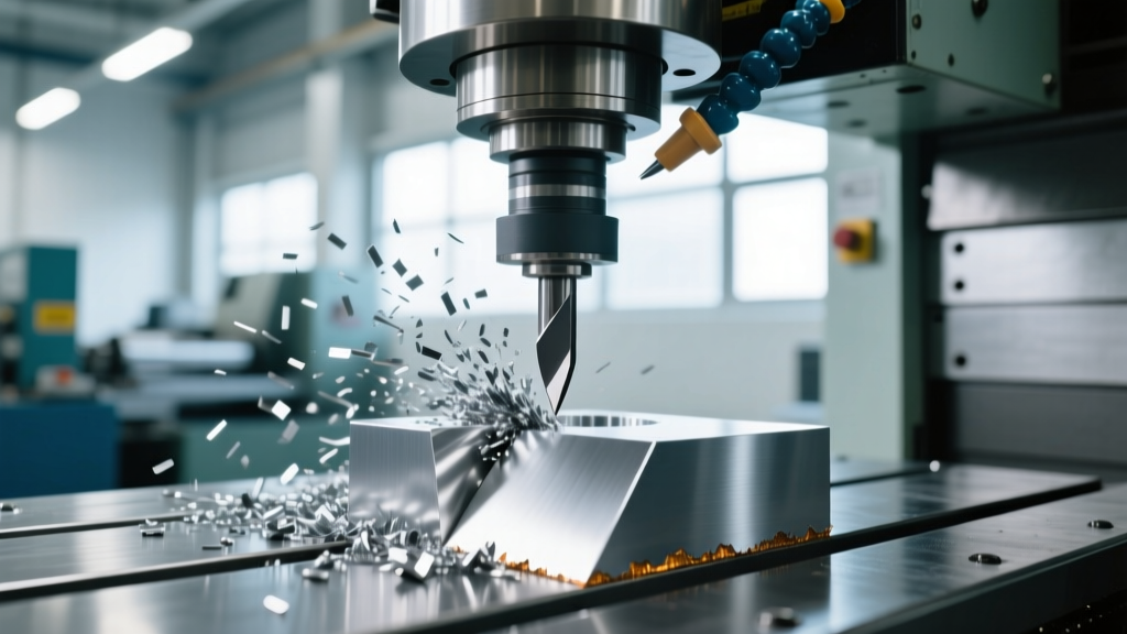
Chip evacuation is the silent killer of aluminum end mills. Aluminum generates long, stringy chips (especially in 6061-T6) or short, abrasive chips (in high-silicon alloys). If chips remain in the cut, they are recut, work-hardening instantly and snapping the tool. The table below provides baseline parameters for modern carbide tooling using adaptive toolpaths.
| Material | Tool Dia / Flutes | Spindle (RPM) | Feed Rate (IPM) | Chipload | Radial DOC |
|---|---|---|---|---|---|
| 6061-T6 | 0.500" / 3-Flute | 14,000 | 126 | 0.003" | 5% (Trochoidal) |
| 7075-T6 | 0.500" / 3-Flute | 12,500 | 105 | 0.0028" | 5% (Trochoidal) |
| 6061-T6 | 0.250" / 2-Flute | 18,000 | 72 | 0.002" | 10% (Trochoidal) |
| 2024-T3 | 0.500" / 3-Flute | 13,000 | 117 | 0.003" | 5% (Trochoidal) |
Note: These parameters assume a rigid machine setup and high-pressure through-spindle coolant or a directed air-blast. Always perform a test cut and measure chip thickness with a micrometer; chips should be warm to the touch, not hot. If chips are cold, you are rubbing, not cutting—increase the feed rate.
Verifying Machine Tool Rigidity and Spindle Runout
If you have optimized your tooling, toolpaths, and coolant, but are still experiencing poor surface finishes and premature wear, the fault likely lies in the machine tool itself. Aluminum machining is highly unforgiving of spindle runout. Excessive Total Indicator Runout (TIR) causes only one flute of the end mill to do all the cutting, effectively doubling the chipload on that single tooth and causing immediate deflection and breakage.
The Arbor Test Procedure
- Clean the Taper: Wipe the spindle taper and tool holder taper with isopropyl alcohol. Even a 5-micron particle of dust can induce severe runout at high RPMs.
- Mount a Precision Test Arbor: Insert a certified ground test arbor into the spindle. Do not use a standard end mill for this test, as end mills have inherent manufacturing tolerances.
- Measure TIR: Place a high-resolution dial indicator (0.0001" graduation) against the arbor, exactly 1 inch below the gage line. Rotate the spindle by hand.
- Evaluate: For high-speed CNC machine aluminum cutting, the TIR must be less than 0.0002" (5 microns). If it exceeds 0.0004", the spindle bearings are worn, or the tool holder retention knob is pulling the taper unevenly.
Furthermore, evaluate your tool holder interface. While BT40 and CAT40 holders are standard, they rely solely on the taper for radial rigidity. For aggressive aluminum roughing, upgrading to an HSK-63A interface provides dual-contact (face and taper) clamping, drastically reducing radial deflection and allowing for higher metal removal rates without chatter. For more detailed maintenance protocols regarding spindle health and tool holder retention forces, refer to the diagnostic resources provided by Haas Automation's technical service library and the milling knowledge base at Sandvik Coromant.
Climb Milling vs. Conventional Milling
Finally, ensure your CAM software is strictly set to Climb Milling for all aluminum operations. In climb milling, the chip thickness starts at its maximum and decreases to zero. This pushes the cutting heat into the chip, which is then evacuated. In conventional milling, the tool rubs against the material before engaging the cut, work-hardening the aluminum and guaranteeing the formation of Built-Up Edge. The only exception is when machining cast aluminum with a heavy, abrasive skin, where a light conventional milling pass can be used to break through the scale before switching to climb milling for the finishing passes.