What's a CNC Machine's Power Draw? 2026 Setup Guide
Understand what a CNC machine power setup entails. Explore 2026 electrical requirements, VFD sizing, regenerative drives, and NEC wiring rules.
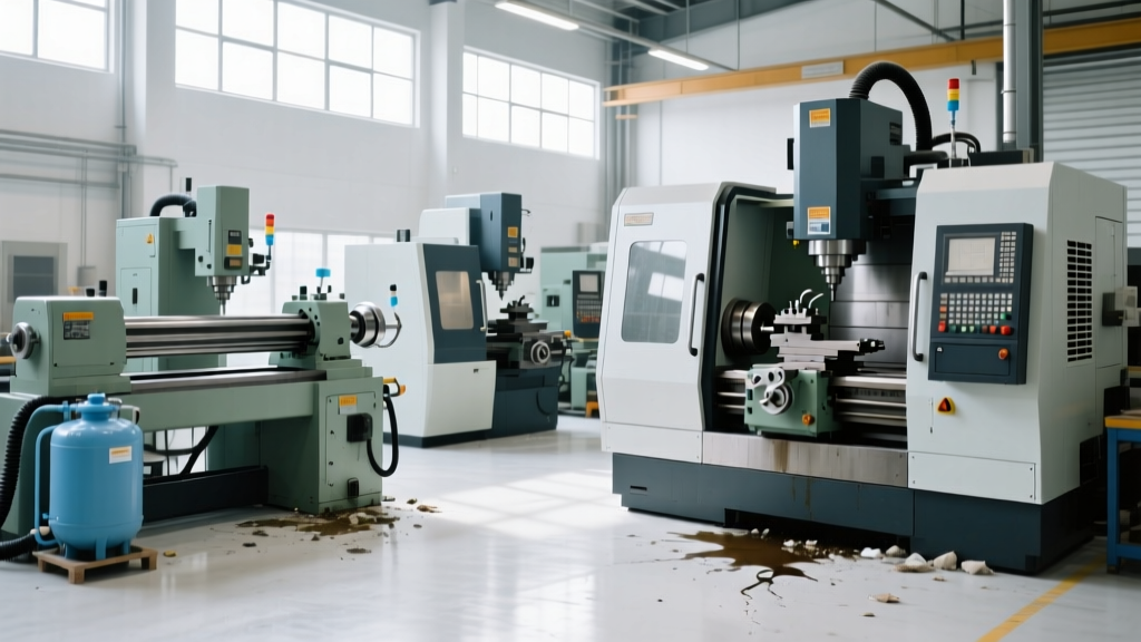
When facility managers and manufacturing engineers ask what's a CNC machine's actual electrical footprint, the answer extends far beyond the nameplate amperage. Modern 5-axis machining centers, multi-tasking lathes, and high-speed routers are complex inductive loads that demand rigorous power quality. A poorly designed electrical setup doesn't just trip breakers; it degrades spindle bearings, corrupts servo drives, and triggers phantom CNC controller alarms.
In 2026, CNC power architecture has shifted from simple 3-phase distribution to intelligent, regenerative ecosystems. This guide details the exact electrical requirements, phase conversion mathematics, and National Electrical Code (NEC) compliance matrices required to commission modern CNC equipment safely and efficiently.
Decoding the Nameplate: kVA, Power Factor, and Inrush Current
The most common mistake in CNC facility planning is sizing the main disconnect based on the machine's kilowatt (kW) rating rather than its kilovolt-ampere (kVA) requirement. CNC servo drives and spindle inverters introduce significant reactive power into the system.
Expert Insight: A machine with a 20 kW spindle motor and a 0.85 power factor actually requires a 23.5 kVA supply capacity. Always size transformers and upstream breakers using the kVA rating listed on the machine's primary electrical enclosure nameplate, not the sum of the individual motor horsepower.Furthermore, you must account for Locked Rotor Amps (LRA) and inrush current. When a direct-on-line (DOL) spindle motor starts, it can draw 600% to 800% of its Full Load Amps (FLA) for a fraction of a second. While modern CNCs use Variable Frequency Drives (VFDs) to soft-start the spindle, the control cabinet's main contactor and the facility's step-down transformer must still handle the initial magnetization inrush of the control transformers without causing a voltage dip that resets the CNC's PLC.
Single-Phase to 3-Phase Conversion: RPC vs. VFD
Many job shops operate in light-industrial zones limited to single-phase 230V power. Running a 3-phase CNC (like a Haas VF-2SS or a Doosan DNM 5700) requires phase conversion. The technology chosen dictates the machine's reliability and the lifespan of its sensitive Fanuc or Mitsubishi drives.
| Conversion Type | Cost (20HP Range) | Voltage Balance | Harmonic Distortion | Best Application |
|---|---|---|---|---|
| Rotary Phase Converter (RPC) | $2,800 - $4,500 | Good (if tuned) | Low | Multiple machines on one bus; manual lathes |
| VFD Phase Converter | $1,400 - $2,500 | Excellent | High (requires filters) | Single dedicated CNC mill or router |
| Static Phase Converter | $600 - $900 | Poor (1/3 power loss) | Moderate | Not recommended for modern CNCs |
The VFD Oversizing Rule
If utilizing a VFD as a phase converter to feed a CNC's internal power supply, you must oversize the VFD by at least 2.0 times the machine's FLA. A VFD rated for 20HP on 3-phase input will overheat and fail rapidly if fed single-phase power at full load, because the single-phase rectifier diodes carry the entire current load. Always consult the NEMA MG 1 Standard for derating curves when applying single-phase input to 3-phase drives.
2026 Innovations: Regenerative Drives and Common DC Buses
The most significant shift in CNC electrical requirements over the last few years is the widespread adoption of Active Front End (AFE) regenerative drives. Historically, when a CNC axis decelerated or a spindle braked, the kinetic energy was converted into heat and burned off via massive dynamic braking resistors mounted on the machine's roof.
Today, systems like the Siemens SINAMICS S120 and Fanuc ai-series utilize common DC bus architectures with regenerative line modules. When the Z-axis drops a heavy fixture or the spindle reverses direction, the kinetic energy is converted back into electrical energy and either:
- Fed back into the facility's AC grid (requiring a regenerative-compatible main breaker).
- Shared across the common DC bus to power other accelerating axes simultaneously.
According to data from the U.S. Department of Energy Advanced Manufacturing Office, regenerative drive setups in high-cycle CNC environments can reduce total machine energy consumption by 15% to 30%, fundamentally altering the ROI calculation for facility electrical upgrades.
IoT Power Monitoring and Motor Current Signature Analysis
Modern CNC electrical setups now integrate IoT power monitoring directly at the main disconnect. Devices like the Schneider Electric PowerLogic PM5 series or Fluke PQ3100 sensors monitor not just total power draw, but the harmonic spectrum of the current.
By utilizing Motor Current Signature Analysis (MCSA), facility engineers can detect micro-fractures in spindle bearings or broken rotor bars in coolant pumps weeks before a catastrophic failure occurs, simply by analyzing the specific frequency anomalies in the power draw waveform.
This predictive maintenance approach requires the electrical panel to be equipped with Ethernet/IP or PROFINET gateways, adding a low-voltage 24V DC network requirement to the traditional high-voltage CNC power setup.
NEC Article 430 Compliance and Wire Sizing Matrix
Sizing conductors for CNC machinery falls under Article 430 of the NFPA 70 (National Electrical Code). Because CNCs are considered continuous duty motor loads with complex control circuits, the branch circuit conductors must be sized at 125% of the machine's full-load current rating.
Below is a standard wire sizing matrix for 75°C rated THHN copper conductors feeding common CNC voltage configurations:
| Machine FLA (Nameplate) | Min. Wire Size (AWG/kcmil) | Max Inverse Time Breaker | Typical CNC Application |
|---|---|---|---|
| 15A - 20A | 12 AWG | 35A | Desktop 3-axis mills, small routers |
| 21A - 30A | 10 AWG | 50A | Standard VMCs (e.g., Haas VF-2) |
| 31A - 40A | 8 AWG | 70A | Heavy-duty VMCs, 5-axis trunnions |
| 41A - 55A | 6 AWG | 90A | Large horizontal boring mills |
| 56A - 70A | 4 AWG | 125A | Multi-tasking lathes, gantry mills |
Grounding, Isolation, and Preventing Phantom Alarms
Perhaps the most overlooked aspect of CNC electrical setup is the grounding topology. Modern CNC controllers are hyper-sensitive to electrical noise, voltage transients, and ground loops. A poor ground can manifest as intermittent servo alarms (such as Fanuc SV0401 or Siemens F30001 faults) that disappear when an electrician checks the voltage with a multimeter.
To ensure signal integrity for high-resolution absolute encoders (which operate on micro-voltage signals), the electrical setup must include:
- Isolated Ground (IG) Receptacles: Run a dedicated, insulated green grounding conductor directly from the machine's grounding bus back to the facility's main grounding electrode system, bypassing any intermediate panel grounds.
- Drive Isolation Transformers: If the facility experiences frequent voltage sags or heavy harmonic distortion from neighboring welders or laser cutters, install a dedicated Delta-Wye isolation transformer upstream of the CNC. This creates a separately derived system, providing a clean sine wave and a localized neutral-to-ground bond.
- Shielded VFD Cables: All power cables running from the CNC's internal spindle drive to the spindle motor must be symmetrical, shielded VFD cables (e.g., 3-core with 3 symmetric ground wires). The shield must be grounded at the drive end using a 360-degree shield clamp, not a pigtail wire, to prevent high-frequency common-mode currents from radiating into the machine's encoder cables.
Understanding what's a CNC machine's true electrical requirement means looking past the basic voltage and amperage. By implementing regenerative drive compatibility, precise NEC-compliant wire sizing, and rigorous grounding topologies, manufacturers can eliminate electrical downtime and maximize the precision capabilities of their 2026 machining fleet.