Work Envelope Innovations: Insights from a Flex CNC Drilling Machine Distributor on Bed Sizing
Discover 2026 work envelope and bed size trends for flexible CNC drilling. Learn how distributors evaluate dynamic footprints, Z-axis clearance, and ROI.
The Decoupling of Physical Bed Size and Usable Work Envelope
In modern manufacturing, the physical dimensions of a machine bed no longer dictate the limits of its machining capabilities. When engaging a flex cnc drilling machine distributor, manufacturers frequently encounter a critical terminology gap: confusing the static cast-iron or welded-steel bed footprint with the dynamic, usable work envelope. In 2026, flexible CNC drilling systems—designed for variable hole patterns in aerospace composites, structural steel, and high-volume woodworking—rely on advanced kinematics that decouple these two metrics entirely.
Historically, a machine with a 2,000mm x 4,000mm bed offered a slightly smaller work envelope due to gantry thickness and spindle housing limits. Today, innovations in moving-column designs, cantilevered gantries, and automated index-drilling shuttle tables mean a machine with a compact 2,000mm x 3,000mm physical footprint can seamlessly process workpieces exceeding 12,000mm in length. This shift is driven by the need to minimize factory floor real estate while maximizing part throughput, a core focus of current National Institute of Standards and Technology (NIST) guidelines on smart manufacturing facility optimization.
Technical Definition: Index Drilling in Flex CNC SystemsIndex drilling allows a machine to drill a series of holes along a workpiece longer than the machine's physical X-axis travel. The machine drills a section, the part is automatically clamped, the gantry returns to a home datum, the material is fed forward via integrated servo-driven rollers, and the process repeats. This requires sub-micron linear encoder feedback to maintain ±0.03mm positional accuracy across the splice points.
2026 Architecture Matrix: Static Beds vs. Dynamic Envelopes
Selecting the right architecture depends entirely on the material handling requirements and the maximum part geometry. A specialized flex cnc drilling machine distributor will typically map the required part envelope against the following machine configurations before quoting a system.
| Machine Architecture | Physical Bed Footprint | Max Work Envelope (X-Y-Z) | Drive System | 2026 Base Price Range |
|---|---|---|---|---|
| Fixed Gantry / Moving Table | 3,500mm x 2,500mm | 2,000mm x 1,500mm x 400mm | Precision Ball Screws | $145,000 - $185,000 |
| Moving Gantry / Fixed Bed | 6,000mm x 3,000mm | 4,500mm x 2,200mm x 600mm | Helical Rack & Pinion | $210,000 - $260,000 |
| Moving Column / Shuttle Table | 4,000mm x 3,000mm | Infinite X (Index) x 2,500mm x 800mm | Linear Motors (X/Y) | $320,000 - $410,000 |
Z-Axis Clearance and the 5-Axis Tooling Penalty
While X and Y axes dictate the footprint of the material, the Z-axis dictates the complexity of the features you can drill. In flexible CNC drilling, particularly for aerospace aluminum extrusions or structural steel beams, 5-axis drilling heads are increasingly standard. However, these multi-axis heads introduce a massive 'tooling penalty' to the Z-envelope.
Calculating True Z-Depth
If a distributor quotes a machine with an 800mm Z-axis travel, that number is largely meaningless without accounting for the spindle housing and tooling length. A standard 5-axis flex drilling head (such as those utilizing HSK63F tapers for high-speed routing and drilling) can consume 350mm to 450mm of vertical space just to house the rotary axes and collision sensors. Consequently, an 800mm travel yields only 350mm of usable vertical drilling depth. For deep-web structural beams, manufacturers must specify machines with 1,200mm+ Z-travel or request custom drop-gantry extensions, which typically add $45,000 to the capital equipment cost.
"The most common cause of post-installation downtime in flex drilling cells is Z-axis collision. Buyers focus on the X-Y table size, but fail to calculate the swing radius of a 5-axis head when tilting to 45 degrees to drill web holes in structural I-beams. Always demand a 3D kinematic simulation from your distributor before signing the PO."
— Lead Applications Engineer, Structural Steel Automation Division
Facility Footprint: The Hidden Envelope Cost
The work envelope of the machine is only half the spatial equation; the operational envelope required on the factory floor is the other. According to research published by the Society of Manufacturing Engineers (SME) regarding flexible manufacturing cells, the physical machine footprint often represents less than 40% of the total required floor space.
When sizing a flex CNC drilling cell, you must allocate space for:
- Material Infeed/Outfeed Conveyors: For a machine processing 12-meter beams, you need a minimum of 14 meters of clear floor space on both the X-axis infeed and outfeed sides, plus 1.5 meters of lateral clearance for operator access.
- Chip and Coolant Management: High-volume flex drilling generates massive swarf. Automated chain-belt conveyors and central coolant filtration units require an additional 3x4 meter footprint, usually positioned at the rear or side of the main bed.
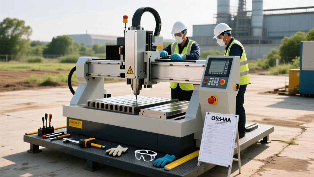
- Safety Light Curtains and Fencing: OSHA and CE compliance require physical barriers or light curtains placed at least 1.2 meters away from the maximum reach of any automated loading crane or robotic arm integrated with the machine.
Financial Mechanics of Envelope Expansion
Expanding the work envelope after the initial purchase is financially punitive. The structural integrity of the machine bed relies on stress-relieved castings or precision-welded steel bases that are machined as a single unit. If you attempt to extend the X-axis bed later, you must dismantle the machine, ship the base back to the OEM for re-machining, and recalibrate the linear guides—a process that routinely exceeds $85,000 and requires three weeks of downtime.
Instead, 2026 best practices dictate purchasing a 'modular base' architecture. These systems feature standardized bed segments that can be bolted and doweled together on-site. While the initial capital outlay for a modular base is 12% to 15% higher than a monolithic casting, it allows a distributor to add 2-meter X-axis extensions in the field for approximately $28,000 per segment, completed over a single weekend.
Distributor Sizing Framework: A Step-by-Step Evaluation
To ensure you procure a flex CNC drilling machine that perfectly aligns with your production realities, utilize this evaluation framework when consulting with your distributor:
- Map the Absolute Maximum Part Geometry: Do not size the bed for your average part. Size the X-Y envelope for the largest 5% of your part catalog, and utilize index-drilling protocols for the extreme outliers.
- Audit the Z-Axis Tooling Stack: Require the distributor to provide a CAD model of the specific 5-axis head and tool holder combination. Measure the distance from the spindle nose to the lowest point of the collision sensor at a 45-degree tilt.
- Evaluate the Drive System for Envelope Length: If your required X-envelope exceeds 3,000mm, reject ball-screw drives due to whip and thermal expansion. Mandate helical rack-and-pinion or linear motor drives with absolute linear encoders.
- Simulate the Material Flow: Run a discrete event simulation (DES) of your shop floor. Ensure the machine's automated loading cycle time does not bottleneck the upstream sawing or downstream welding stations.
- Lock in the Modular Base Option: If your product roadmap indicates longer assemblies within the next 36 months, negotiate the inclusion of pre-machined dowel holes and cable-track extensions on the base unit during the initial build.
By shifting the focus from static bed dimensions to dynamic, system-wide work envelopes, manufacturers can significantly improve capital efficiency and eliminate the spatial bottlenecks that plague legacy drilling operations.