Drill Machine CNC Controller Types: Operator Training Guide
Master drill machine CNC controller types and interfaces. This operator training guide covers Fanuc, Siemens, and Haas best practices for peak precision.
The Core Architecture of Drill Machine CNC Interfaces
Operating a drill machine CNC requires more than memorizing G-code; it demands a deep understanding of the controller's architecture and human-machine interface (HMI). The controller acts as the brain, interpreting CAD/CAM toolpaths into precise servo-motor movements. For training purposes, operators must distinguish between the control kernel (the real-time operating system managing interpolation and servo loops) and the interface layer (the visual and tactile environment where the operator inputs offsets, manages tool tables, and monitors execution).
Training Callout: Kernel vs. InterfaceA common training failure is teaching operators to rely solely on the visual interface without understanding the underlying kernel state. If the HMI displays a safe Z-coordinate but the kernel's modal state is trapped in incremental mode (G91), the next canned cycle will result in a catastrophic spindle crash. Always train operators to verify modal states via the 'Active Codes' diagnostic page before cycle start.
Dominant Controller Ecosystems in CNC Drilling
Different manufacturers utilize distinct controller ecosystems, each with unique workflows for drilling operations. Cross-training operators across these platforms requires focusing on their specific handling of canned cycles and rigid tapping.
Fanuc 0i-F Plus & 31i-B Series
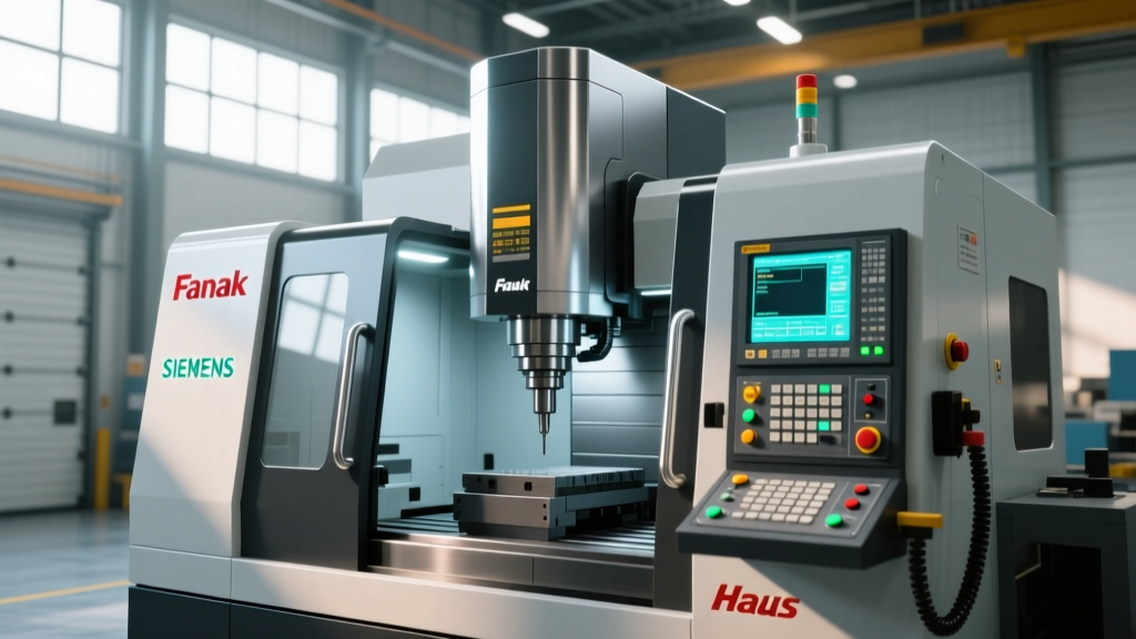
Fanuc remains the industry standard for multi-spindle and high-speed drill machine CNC setups. The 0i-F Plus is prevalent in standard vertical drilling centers, while the 31i-B handles complex 5-axis simultaneous drilling. Fanuc interfaces rely heavily on traditional G-code modal states. For rigid tapping (G84), operators must understand that the spindle transitions from speed control to position control. If Parameter 5200#0 is not correctly enabled by maintenance, the machine will alarm out or snap the tap. Training must emphasize checking the 'Diagnos' page (address 0400+) to verify spindle synchronization error margins during tapping cycles.
Siemens Sinumerik 840D sl
Siemens controllers utilize a vastly different HMI, prioritizing graphical programming via ShopTurn/ShopMill alongside traditional ISO dialects. For drill machines, Siemens uses specific cycles like CYCLE81 (standard drilling) and CYCLE83 (deep hole peck drilling). The Sinumerik interface features a 'ProgramGuide' that visually prompts operators for cycle parameters (e.g., clearance plane, depth, dwell time), significantly reducing syntax errors. However, operators transitioning from Fanuc often struggle with Siemens' coordinate transformation concepts, such as TRANS/ATRANS, which shift the local coordinate system for angled hole drilling.
Haas NGC (Next Generation Control)
The Haas NGC interface is renowned for its user-friendly Visual Quickcode (VQC) system. On Haas drill machines (like the DT-1 or DM-1), operators can build peck drilling and tapping routines using on-screen prompts without writing raw G-code. A critical training focus for NGC is Setting 34 (Tool Change Position) and the Wireless Intuitive Probing System (WIPS). Operators must be trained to use the macro variables (#100-#149) exposed in the NGC interface to dynamically adjust drill depths based on real-time probe feedback.
Controller Interface Comparison Matrix
| Controller Model | Primary Drilling Interface | Rigid Tapping Setup | Operator Learning Curve |
|---|---|---|---|
| Fanuc 0i-F Plus | Manual Data Input (MDI) / G-Code | G84 with M29 prefix | Moderate (Requires strong G-code logic) |
| Siemens 840D sl | ShopMill Graphical / CYCLE83 | CYCLE84 (Integrated GUI) | Steep (Complex parameter menus) |
| Haas NGC | Visual Quickcode (VQC) | G84 (Auto-synchronized) | Low (Highly intuitive GUI) |
Operator Training Best Practices: Navigating Modal Traps
The most frequent cause of spindle crashes on a drill machine CNC is the mismanagement of modal G-codes. Unlike turning centers where toolpaths are often distinct, drilling relies on repetitive canned cycles that inherit modal states from previous operations.
⚠️ Critical Warning: The G90/G91 Z-Axis TrapIf an operator uses G91 (Incremental) to jog the tool for a manual edge find, and forgets to reinstate G90 (Absolute) before calling a G83 Peck Drilling cycle, the Z-axis will interpret the R-plane (retract plane) as an incremental move from the current position. This drives the drill directly into the workpiece or vise at rapid traverse (G00) speeds.
Standardized Safe Power-Up Sequence
To mitigate modal traps, implement this strict 4-step power-up sequence in your operator training curriculum:
- Cancel Active Cycles: Input
G80(Cancel Canned Cycle) in MDI mode immediately after homing. - Reset Modal States: Input
G90 G17 G40 G49 G80to force Absolute positioning, XY plane selection, cutter comp cancellation, tool length comp cancellation, and cycle cancellation. - Verify Work Offsets: Navigate to the Offset/Setting page and visually confirm that G54-G59 Z-values are negative (standard for vertical drill machines where the spindle moves down toward the part).
- Dry Run with Z-Shift: Apply a +2.000 inch Z-axis work shift for the first part run, forcing the machine to drill in the air above the part to verify hole locations and depth calculations.
Troubleshooting Interface Alarms on CNC Drill Machines
Operators must be trained to read controller alarms not just as errors, but as diagnostic data. According to the Society of Manufacturing Engineers (SME), efficient alarm resolution reduces machine downtime by up to 22% per shift.
Common Drill-Specific Alarms and Resolutions
- Fanuc Alarm 203 (Spindle Orientation Error): Occurs during rigid tapping or tool changes. Resolution: Check the spindle drive belt tension and verify the orientation sensor (proximity switch or encoder) is free of coolant debris.
- Haas Alarm 114 (Z Axis Overtravel): Triggered when a drill length offset is entered incorrectly, driving the tool past the soft limit. Resolution: Press 'RESET', jog Z upward in handle mode, and verify the tool geometry offset against the physical tool presetter data.
- Siemens Alarm 61150 (Tool Radius Too Large for Hole): The controller's collision detection recognizes the programmed drill diameter exceeds the bore size in the CAD model. Resolution: Cross-reference the tool table diameter parameter against the CYCLE83 programmed diameter.
Upgrading and Retrofitting Legacy Drill Machine CNC Controllers
When training on older equipment, operators face the challenge of outdated interfaces lacking modern safety interlocks. Retrofitting a legacy drill machine CNC with a modern controller (such as upgrading an old Fanuc 10T to a 0i-F Plus or installing a Centroid Acorn CNC retrofit) typically costs between $18,000 and $35,000, depending on servo-drive compatibility.
"Retrofitting isn't just about faster processing; it's about interface safety. Modern controllers enforce mandatory tool-length verification prompts and graphical toolpath verification that legacy systems simply cannot support. The ROI is realized in prevented crashes, not just cycle time reduction." — Manufacturing Engineering Lead, OSHA Metalworking Safety Guidelines compliance auditor.
For shops hesitant to invest in hardware retrofits, implementing PC-based CNC simulator software (like CNC Simulator Pro or VERICUT) allows operators to practice interface navigation and G-code editing for approximately $150 to $800 per annual license, bridging the gap between legacy hardware and modern training methodologies.
FAQ: Drill Machine CNC Controller Operations
Why does my drill machine CNC alarm out during G84 rigid tapping but works fine in G81 drilling?
G81 only requires spindle speed control (RPM). G84 rigid tapping requires the controller to synchronize the spindle's exact rotational position with the Z-axis linear feed. If the spindle encoder feedback is degraded, or if the specific rigid tapping parameter (e.g., Fanuc Param 5200) is disabled, the controller cannot maintain the precise pitch-to-feed ratio and will trigger a synchronization alarm.
How do I handle deep hole chip evacuation on a Siemens controller?
Use CYCLE83 instead of CYCLE81. CYCLE83 includes parameters for peck depth (FDEP), dwell time at the bottom of the hole to clear chips, and a retract distance for coolant flow. Ensure the 'VARI' parameter is set to 1 for chip breaking (retracts inside the hole) or 2 for full chip evacuation (retracts to the clearance plane).