How CNC Machines Produce Both 2D and 3D Objects Across Bed Sizes
Compare CNC machine bed sizes and work envelopes to optimize 2D and 3D production. Explore 2026 tech trends expanding volumetric machining limits.
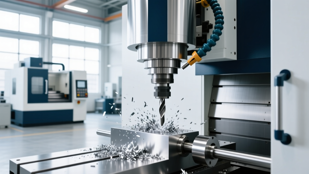
As a foundational principle of modern manufacturing, CNC machines can produce both two-dimensional and three-dimensional objects. However, the physical boundaries of the machine bed and work envelope strictly dictate the complexity, scale, and economic viability of those parts. While a massive waterjet can slice intricate 2D profiles from a 10-foot sheet of titanium, it cannot mill a 3D turbine blade. Conversely, a highly precise 5-axis machining center can sculpt complex volumetric geometries but is severely limited by its compact XYZ travel constraints.
In 2026, the gap between planar (2D/2.5D) processing and full volumetric (3D/5-axis) machining is being bridged by modular workholding, kinematic extensions, and AI-driven volumetric compensation. Understanding how bed size correlates to dimensional output is critical for capital equipment investment and production planning.
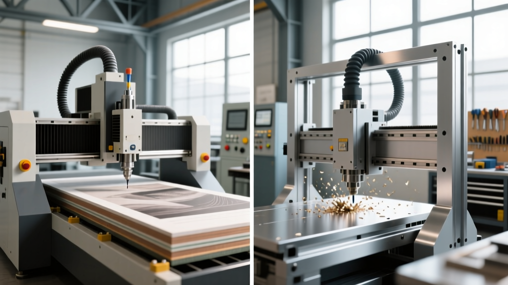
2026 Envelope Data Highlight:Planar (2D) machines prioritize XY footprint, often exceeding 100 sq. ft. of cutting area with minimal Z-axis travel (under 10 inches). Volumetric (3D) machines prioritize Z-axis clearance and trunnion dynamics, typically operating within a dense 15 to 30 sq. ft. footprint but requiring massive structural rigidity to maintain tolerances across simultaneous multi-axis movements.
Defining the Work Envelope: Planar vs. Volumetric Constraints
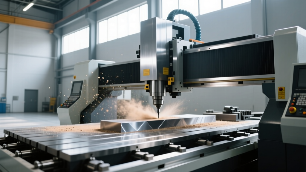
The work envelope is the maximum three-dimensional space the cutting tool can reach relative to the workpiece. For 2D production (laser cutting, waterjet, plasma, or 2.5D routing), the Z-axis is largely static, used only for pierce height control or basic tool clearance. The primary constraint is the XY bed size. According to the Society of Manufacturing Engineers (SME), optimizing 2D production requires maximizing nestable surface area to reduce material waste and setup times.
For 3D production (3-axis contouring, 4-axis indexing, and 5-axis simultaneous milling), the envelope becomes a volumetric sphere or cylinder. The limitation is rarely the raw XY table size, but rather the distance from the spindle gauge line to the center of rotation on a trunnion table. A machine with a 40-inch Y-axis travel might only accommodate a 20-inch diameter 3D part if the trunnion table restricts the rotational swing radius.
2026 Machine Bed & Envelope Comparison Matrix
The following matrix contrasts standard 2026 machine models across the 2D-to-3D spectrum, highlighting how bed size and pricing scale with dimensional capability.
| Machine Model | Type & Axes | Work Envelope (XYZ) | Primary Dimensionality | Approx. 2026 Base Price |
|---|---|---|---|---|
| OMAX 55100 | Abrasive Waterjet (3-Axis) | 55" x 100" x 8" | 2D Planar / Bevel | $145,000 |
| Haas VF-2SS | Vertical Machining Center (3-Axis) | 30" x 16" x 20" | 2.5D / Prismatic 3D | $72,000 |
| DMG MORI DMU 50 3rd Gen | 5-Axis Simultaneous VMC | 500 x 450 x 400 mm | Complex 3D Volumetric | $265,000 |
| Mazak INTEGREX i-200S | Multi-Tasking Mill-Turn | Ø26" x 40" (Swing/Turn) | 3D + Rotational Turn | $480,000 |
Technology Trends Expanding Volumetric Limits
Historically, if a 3D part exceeded the machine bed, it required splitting the part, welding it post-machining, or purchasing a vastly more expensive gantry mill. In 2026, advanced manufacturing facilities leverage specific technologies to artificially expand the work envelope without buying larger cast-iron beds.
Kinematic Extensions and Robotic Tending
For massive 3D objects like wind turbine blade molds or aerospace composite mandrels, shops are deploying 6-axis robotic arms (such as the KUKA KR Quantec series) equipped with high-speed spindle end-effectors. By mounting the stock on a static floor bed and using the robot's kinematic reach, the effective work envelope becomes virtually infinite. According to research published via the NIST Advanced Manufacturing Portal, integrating laser-tracker feedback loops with robotic CNC arms now holds volumetric tolerances to ±0.005 inches over a 20-foot span, a feat impossible a decade ago.
Modular Tombstone Grids and Z-Axis Stacking
On standard 3-axis beds like the Haas VF series, operators maximize 3D volumetric output using high-density modular tombstones. By utilizing standard 1.5-inch grid hole patterns and hydraulic clamping, shops can stack multiple 3D prismatic parts vertically within the Z-axis travel. This effectively multiplies the machine's volumetric output per cycle without requiring a larger XY bed footprint, drastically reducing the cost-per-part for complex brackets and fittings.
The Z-Axis Clearance Trap: A Common 3D Machining Failure
WARNING: Spindle Crash Risk During ATC CyclesA frequent error when transitioning from 2D to 3D machining is miscalculating the Z-axis clearance required for the Automatic Tool Changer (ATC).
The Math: If your VMC has a maximum spindle-nose-to-table distance of 24 inches, and you are machining a 12-inch tall 3D part, you have 12 inches of space remaining at Z-zero (part top). If your tool assembly (holder + cutting tool) is 9 inches long, you only have 3 inches of physical clearance. If the machine's ATC mechanism requires a 5-inch clearance plane to execute a tool swap safely, the spindle will crash into the part or the tool will snap during the tool change cycle. Always map your Z-axis retract planes against the physical tool assembly length, not just the raw part height.
Decision Framework: Matching Bed Size to Dimensionality
Selecting the correct CNC bed size requires analyzing the dimensional reality of your part catalog, not just the maximum theoretical part size. Use the Association For Manufacturing Technology (AMT) guidelines for capital equipment justification to apply this framework:
- Scenario A: 80% Flat/2D Parts (Gaskets, Brackets, Sheet Metal Enclosures)
Action: Prioritize raw XY bed area over Z-axis travel and spindle RPM. Invest in a large-format waterjet or laser cutter (e.g., 60" x 120" bed). The ROI is driven by nesting software efficiency and material utilization, not volumetric complexity. - Scenario B: Complex 5-Sided 3D Parts (Impellers, Aerospace Valves, Medical Implants)
Action: Prioritize trunnion table diameter and Z-axis clearance over raw XY table size. A 5-axis machine with a 20-inch trunnion and 24-inch Z-travel will out-produce a massive 3-axis bed machine because it eliminates secondary setups and 5-axis kinematic extensions allow access to undercuts. - Scenario C: High-Mix, Low-Volume Prismatic 3D (Hydraulic Manifolds, Custom Housings)
Action: Invest in a standard 3-axis VMC bed paired with an automated pallet changer (APC) and multi-axis tombstones. This allows the machine to cut 3D features on multiple sides of a part by indexing the tombstone, maximizing the existing work envelope without the premium cost of a 5-axis trunnion table.
Ultimately, the capability to produce both 2D and 3D objects is defined not just by the controller's G-code processing power, but by the physical geometry of the machine bed. Aligning the work envelope with the specific dimensional requirements of your production mix ensures maximum spindle utilization and prevents catastrophic clearance failures.