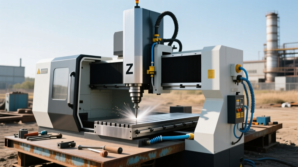
How CAM Programs for CNC Machines Impact Aluminum Spindle Maintenance
Discover how optimizing CAM programs for CNC machines reduces spindle wear and extends service intervals during high-speed aluminum machining operations.
Machining aluminum alloys like 6061-T6 and 7075-T6 is often perceived as forgiving due to the material's low cutting forces and high machinability. However, the aggressive feed rates and high spindle speeds required for aluminum production milling introduce severe harmonic vibrations and thermal cycling. The hidden variable dictating the lifespan of your spindle bearings, ball screws, and way covers is not just the physical tooling, but the specific toolpath strategies generated by your CAM programs for CNC machines. Mismanaged G-code output accelerates mechanical degradation, turning standard 5,000-hour preventative maintenance (PM) intervals into emergency 2,000-hour rebuilds.
⚠️ Maintenance Alert: Running traditional offset toolpaths in 7075-T6 aluminum at 12,000+ RPM generates harmonic chatter that degrades ceramic hybrid spindle bearings up to 40% faster than constant-engagement adaptive toolpaths. Vibration RMS values exceeding 2.8 mm/s (per ISO 10816-3) mandate immediate spindle teardown.The Aluminum Machining Paradox: High Speed vs. Mechanical Degradation
Aluminum requires high surface speeds (often 3,000 to 10,000 SFM) to prevent built-up edge (BUE) and ensure proper chip evacuation. To achieve this on standard VMCs with 12,000 RPM or 15,000 RPM spindles, programmers must utilize small-diameter end mills (e.g., 3/8" or 1/2" carbide) at maximum spindle velocity. While the radial cutting forces are lower than steel, the sheer frequency of cutting-edge impacts creates high-frequency acoustic emissions. If the CAM software outputs sharp directional changes without adequate corner blending or jerk-control commands, the resulting inertial shock loads transfer directly through the tool holder into the spindle cartridge's angular contact bearings.
According to Harvey Tool's technical guidelines on high-efficiency milling (HEM), maintaining a consistent radial chip thickness is critical not just for tool life, but for machine stability. When CAM programs for CNC machines rely on legacy zig-zag or offset contouring, the tool experiences momentary spikes in radial engagement at corners and slot entries. These micro-shocks cause microscopic brinelling on the spindle bearing raceways, a failure mode that is entirely preventable through advanced CAM toolpath selection.
How Specific CAM Toolpaths Dictate Service Intervals
Modern CAM platforms like Mastercam (Dynamic Motion), Fusion 360, and Siemens NX offer toolpaths designed to maintain constant tool engagement. Understanding how these specific algorithms interact with your machine's mechanical drivetrain is essential for adjusting your PM schedule.
Adaptive Clearing and X/Y Axis Ball Screw Wear
Adaptive clearing maintains a constant radial engagement (typically 8% to 15% of the tool diameter) while varying the feed rate and step-over dynamically. Because the cutting force vector remains remarkably stable, the thrust bearings on the X and Y axis ball screws experience uniform loading. Shops utilizing adaptive CAM programs for CNC machines can safely extend ball screw backlash inspection intervals from 1,000 hours to 2,500 hours, as the absence of shock-loading prevents premature nut recirculation wear. Target backlash tolerance should remain below 0.0002" for high-precision aerospace aluminum components.
Trochoidal Milling and Z-Axis Thrust Bearing Stress
Trochoidal slotting uses a circular rolling motion to machine slots wider than the tool diameter. While excellent for chip evacuation in deep aluminum pockets, poorly configured trochoidal paths often feature rapid Z-axis retracts at the end of each arc. If the CAM post-processor does not output smooth Z-axis blending commands (such as G64 cutting mode with look-ahead), the Z-axis servo motor and thrust bearings endure high-G deceleration forces. Over time, this causes Z-axis ball screw stretch and thermal drift, necessitating more frequent laser interferometry calibration.
| CAM Toolpath Strategy | Primary Mechanical Stress | Affected Component | PM Interval Adjustment |
|---|---|---|---|
| Traditional Offset / Zig-Zag | High-frequency shock loading at corners | Spindle cartridge bearings | Reduce by 30% (Inspect at 1,500 hrs) |
| Adaptive / HEM Clearing | Constant, low-amplitude radial force | X/Y Axis ball screw nuts | Extend by 50% (Inspect at 2,500 hrs) |
| Trochoidal Slotting | Rapid Z-axis inertial deceleration | Z-axis thrust bearings & servo | Standard (Requires laser cal. at 2,000 hrs) |
| Plunge Roughing | Massive axial thrust loads | Z-axis linear guideways | Increase way-lube flow; inspect blocks at 1,000 hrs |
Coolant Delivery Strategies in CAM and Way Cover Degradation
An often-overlooked maintenance consequence of CAM programming is way cover and bellows degradation caused by chip flushing mechanics. Aluminum chips are notoriously sharp and abrasive. When CAM programs for CNC machines utilize deep peck drilling cycles (e.g., G83) or aggressive retract heights for chip clearing, high-pressure Through-Spindle Coolant (TSC) at 70 bar (1,000 PSI) blasts aluminum fines into the telescopic way covers.
Unlike steel chips, which may bounce off or break down, aluminum fines mix with way lube (such as Mobil Vactra No. 2) to form a highly abrasive slurry. This slurry infiltrates the wiper seals on the X and Y axis way covers, scoring the linear guideway rails. To mitigate this, programmers must configure CAM retract cycles to minimize unnecessary Z-axis clearances and utilize localized air-blast macros (M-codes) instead of relying solely on TSC for chip evacuation during shallow pocketing operations. Haas Automation's service manuals explicitly warn that abrasive slurry ingress is the leading cause of premature linear guide failure in high-production aluminum environments.
Optimizing G-Code Post-Processors to Protect Spindle Cartridges
The physical CAM toolpath is only half the equation; the post-processor's handling of motion control codes directly impacts mechanical wear. When machining aluminum at high feed rates (e.g., 400+ IPM), the machine's servo drives must constantly accelerate and decelerate.
- G61 (Exact Stop Mode): If your post-processor defaults to G61 for contouring, the machine will decelerate to zero at every vector intersection. In aluminum roughing, this causes severe localized dwell, leading to tool deflection, part gouging, and intense shock loading on the axis drives. G61 should be strictly reserved for final finishing passes where corner definition is critical.
- G64 (Cutting Mode / Look-Ahead): Utilizing G64 (or the machine-specific equivalent, such as Haas G187 High-Speed Machining mode) allows the CNC control to blend vectors and maintain constant velocity. This smoothing algorithm drastically reduces the inertial jerk transferred to the machine casting and spindle bearings.
- Jerk Control Parameters: Advanced CAM post-processors allow for the output of jerk-limiting parameters (e.g., Siemens G642 or Fanfo AICC). Capping the jerk limit prevents the servos from demanding instantaneous torque spikes, protecting the motor couplings and ball screw thrust bearings from torsional fatigue.
"We tracked spindle vibration data across 40 VMCs running identical 6061-T6 aerospace parts. The machines running legacy offset toolpaths with G61 exact stop commands required spindle cartridge replacements at an average of 3,800 hours. The machines running adaptive clearing with G64 look-ahead exceeded 8,500 hours before bearing RMS thresholds triggered a rebuild. The software dictates the hardware lifespan."
— Lead Applications Engineer, Tier 1 Aerospace CNC Facility
Revised Preventative Maintenance (PM) Schedule for Aluminum VMCs
Standard OEM maintenance schedules are based on generalized cutting conditions. If your shop is dedicated to high-volume aluminum machining utilizing modern CAM programs for CNC machines, your PM schedule must be recalibrated to address the specific wear profiles of high-speed, low-force cutting.
- Daily (Operator Level): Inspect way cover wipers for aluminum slurry buildup. Flush the TSC union with clean water or specialized spindle flush fluid to prevent aluminum oxide crystallization inside the rotary union seals.
- 500-Hour Interval: Check spindle vibration using a handheld accelerometer. Record RMS velocity on the X, Y, and Z axes. If readings exceed 1.8 mm/s during a standardized 12,000 RPM test cut, schedule a spindle drawbar force check (target > 1,200 lbs for standard CAT40 retention knobs).
- 1,500-Hour Interval (Adaptive Toolpath Shops): Verify X and Y axis ball screw backlash using a dial indicator. Re-tension the ball screw locknuts if backlash exceeds 0.0003". Grease the linear guideway blocks with manufacturer-specified lithium-complex grease (e.g., NSK LG2) if automatic oiling volume is insufficient for high-speed traverses.
- 3,000-Hour Interval: Perform full laser interferometry calibration for positional accuracy and backlash compensation. High-speed aluminum milling often masks thermal growth errors until they result in out-of-tolerance bore locations.
By aligning your CAM programming strategies with a targeted, data-driven maintenance schedule, manufacturing facilities can drastically reduce unplanned downtime. The synergy between intelligent toolpath generation and proactive mechanical upkeep is the defining factor in maximizing the return on investment for high-speed CNC machining centers.