3-Axis CNC Machine for Automotive Industry: Setup & Best Practices
Master 3-axis CNC machine setup for the automotive industry. Learn operator best practices, fixture design, and capability limits for high-volume parts.
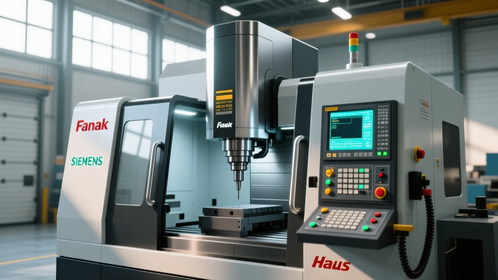
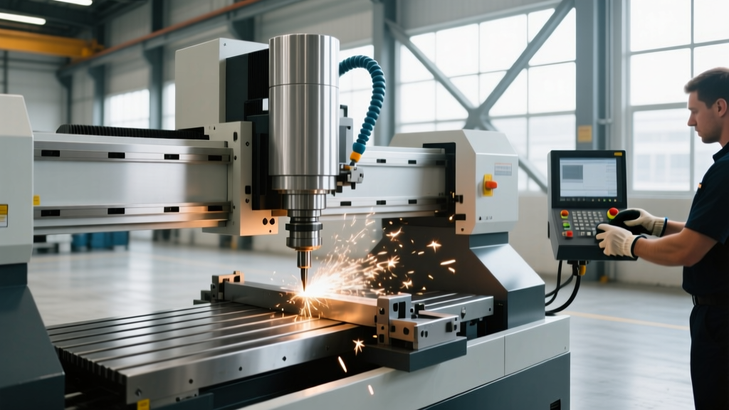
Deploying a 3-axis CNC machine for automotive industry production requires a strict departure from general-purpose job shop habits. High-volume automotive environments demand rigid setup protocols, aggressive but stable material removal rates (MRR), and uncompromising repeatability. While multi-axis platforms dominate complex structural EV components, the 3-axis vertical machining center (VMC) remains the undisputed workhorse for prismatic automotive parts: brackets, flanges, pump housings, and transmission valve bodies.
For machine operators and setup technicians, maximizing the output of platforms like the Haas Automation VF Series or DMG MORI CMX V line requires mastering the intersection of workholding rigidity, thermal management, and in-cycle verification. This guide details the exact setup protocols, tooling parameters, and troubleshooting frameworks required to run automotive components profitably and within tight OEM tolerances.
Core Capabilities and Application Matrix
A standard 3-axis VMC with a 40" x 20" x 20" envelope and a 12,000 RPM direct-drive spindle is highly capable, provided the part geometry aligns with the machine's kinematic limits. Automotive engineers frequently attempt to consolidate features onto single castings to reduce assembly time, which can inadvertently push parts outside 3-axis capabilities.
| Automotive Component | Typical Material | 3-Axis Viability | Setup & Workholding Strategy |
|---|---|---|---|
| EV Battery Mounting Bracket | 6061-T6 Aluminum | High | Modular sub-plate with Mitee-Bite Pitbull clamps; single setup. |
| ABS Pump Housing | A380 Die-Cast Aluminum | Medium | Requires dual-setup (Op 10/Op 20) using custom machined soft jaws. |
| Steering Knuckle | Forged 6082 Aluminum | Low | Complex undercuts and multi-angle mounting faces require 4/5-axis or indexing. |
| Transmission Valve Body | 356-T6 Cast Aluminum | High | Hydraulic tombstone or high-density vise array; deep cavity milling. |
Operator Setup Protocol: First-Article to Production Run
In automotive machining, a flawed setup compounds into thousands of scrapped parts. The transition from raw casting to a validated first-article inspection (FAI) must follow a deterministic sequence.
1. Workholding and Indicator Sweeping
Never rely solely on the machine's table T-slots for locating high-volume fixtures. Use a precision ground sub-plate or a dedicated fixture plate with locating pins (e.g., Carr Lane or Bluco modular systems). When using standard milling vises like the Kurt DX6 for lower-volume aftermarket automotive runs, operators must sweep the fixed jaw with a 0.0001" resolution dial indicator. Acceptable runout for automotive prismatic parts is typically ≤ 0.0005" across the entire jaw length. Torque the vise handle to exactly 80 ft-lbs using a calibrated torque wrench to ensure consistent clamping force without inducing elastic deformation in thin-walled castings.
2. Work Coordinate System (WCS) and Probe Calibration
Automotive OEMs frequently mandate geometric dimensioning and tolerancing (GD&T) datums that do not align with the physical edges of the raw casting. Utilizing a spindle-mounted probe, such as the Renishaw OMP60, is non-negotiable for setting the WCS. Operators should program a 4-point bore centroid routine or a 3-point plane routine to establish the Z-axis datum, compensating for casting thickness variations that can exceed ±0.030".
⚠️ Warning: Thermal Expansion in Aluminum AlloysAluminum expands at approximately 13 µm/m·°C. If your shop ambient temperature fluctuates from 68°F (20°C) at night to 85°F (29°C) during a summer shift, a 12-inch long EV battery bracket will grow by roughly 0.0035 inches. For tight-tolerance automotive fits, operators must run a warm-up cycle to stabilize the spindle and ballscrews, and utilize in-cycle probing to update tool offsets dynamically as the machine thermally stabilizes.
Tooling Selection for High-Volume Automotive Alloys
The automotive industry relies heavily on specific alloy families, each demanding distinct tooling geometries and coatings. Referencing Sandvik Coromant's milling knowledge base reveals that matching the tool substrate to the specific abrasive nature of the casting is critical for edge life.
- A380 Die-Cast Aluminum (High Silicon): Contains 8-10% silicon, which is highly abrasive. Standard uncoated carbide will wear rapidly. Operators must use CVD diamond-coated endmills or PCD (Polycrystalline Diamond) inserted tools for finish passes to maintain surface finishes below 63 Ra µin.
- 6061-T6 Billet (Prototyping/Aftermarket): Highly gummy. Use uncoated, mirror-polished carbide endmills with a high rake angle (e.g., Kennametal HARVI II Al) to prevent built-up edge (BUE). Run high surface speeds (SFM 2500+) with aggressive chip loads.
- G3000 Cast Iron (Brake Rotors/Housings): Generates abrasive dust, not chips. Use thick-honed edge carbide inserts with Al2O3 (aluminum oxide) coatings. Avoid high-pressure coolant directly on the cutting edge during interrupted cuts to prevent thermal shock and micro-chipping.
Troubleshooting Common 3-Axis Automotive Failure Modes
When cycle times are pushed to the limit, specific failure modes emerge. Use this diagnostic framework to isolate and resolve issues on the shop floor.
Scenario A: Severe Chatter on Thin-Wall Bracket Features
- Cause: Harmonic resonance between the tool overhang and the unsupported thin wall (often < 3mm thick).
- Fix: Switch to a variable helix, variable pitch endmill (e.g., Harvey Tool or Helical Solutions). This disrupts the harmonic frequency. If chatter persists, reduce the radial width of cut (RDOC) to 5% of the tool diameter while maintaining a high axial depth of cut (ADOC) and feed rate.
Scenario B: Premature Tool Failure in Deep Cavity Milling (Valve Bodies)
- Cause: Chip recutting and inadequate coolant penetration at the bottom of a 6-inch deep pocket.
- Fix: Implement trochoidal milling (adaptive clearing) toolpaths to maintain constant tool engagement and ensure the flute has space to evacuate chips. Activate through-tool coolant at a minimum of 700 PSI to blast chips out of the cavity.
Scenario C: Porosity Leaks in Machined Coolant Passages
- Cause: The casting process inherently creates micro-voids. When the CNC machine cuts into these voids, the surface finish degrades, causing O-ring seal failures in the final automotive assembly.
- Fix: Operators cannot fix casting porosity with toolpaths. However, they can mitigate the symptom by using a single-flute, high-polish reamer for the final pass of the bore, effectively 'burnishing' the surface and closing micro-pores to achieve the required sealing surface finish.
Maximizing Uptime: In-Cycle Verification and Automation
In a high-volume automotive contract, a single broken tap or drifted tool offset can result in a crashed machine and hours of downtime. Modern 3-axis CNC setups must integrate automated verification routines.
Operators should program post-process probing routines immediately following critical roughing operations. For example, after rough-milling the main bore of an ABS pump housing, program the Renishaw probe to check the bore diameter. If the probe detects the bore is undersize by 0.002" (indicating tool deflection or insert wear), the machine's macro variables should automatically update the finish tool's wear offset before the semi-finish pass begins. This closed-loop feedback eliminates the need for manual operator intervention and ensures every part meets the ±0.0005" positional tolerance required by the OEM blueprint.
💡 Operator Tip: Tool Breakage DetectionAlways integrate an M-code command (e.g., M190) to trigger a laser tool breakage detector (like the Renishaw TRS2) after any high-risk operation, such as deep-hole peck drilling or tapping blind holes in cast iron. Catching a broken tap before the next tool enters the spindle prevents catastrophic fixture damage and saves thousands of dollars in scrapped automotive castings.
Mastering the 3-axis CNC machine for automotive industry applications is not about running the machine faster; it is about running it smarter. By enforcing rigorous workholding protocols, selecting alloy-specific tooling, and leveraging in-cycle probing to combat thermal and mechanical variables, operators can transform a standard VMC into a highly predictable, high-yield automotive production cell.