Plasma Machine CNC Operator Training: Essential Best Practices
Master your plasma machine CNC with expert operator training. Learn best practices for cut speed, kerf compensation, THC calibration, and safety.
The Physics of the Arc: Cut Speed, Kerf, and Amperage
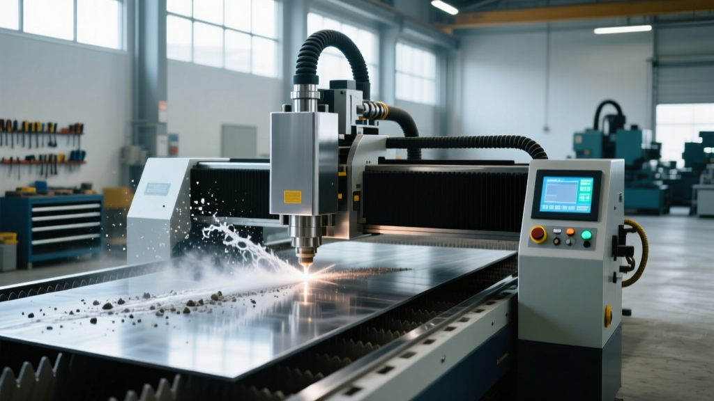
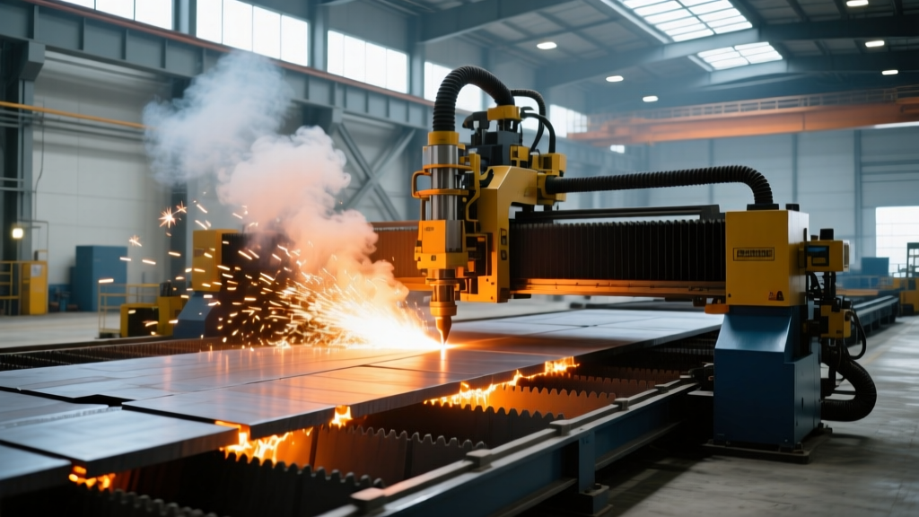
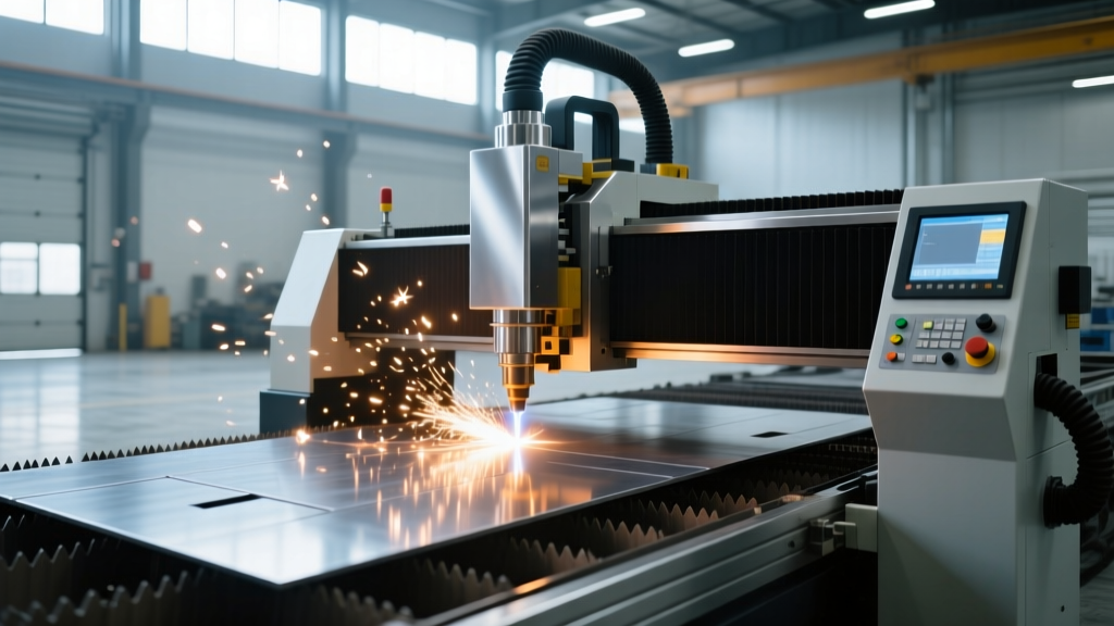
Operating a plasma machine CNC requires more than loading G-code and pressing cycle start; it demands a deep understanding of the thermal dynamics within the plasma arc. Unlike laser or waterjet systems, the plasma arc is a fluid, electrically conductive gas column that responds dynamically to travel speed, torch height, and gas pressure. When an operator fails to balance these variables, the result is excessive dross, shortened consumable life, and compromised edge squareness.
According to Hypertherm's plasma cutting fundamentals, the arc temperature can exceed 20,000°C. Harnessing this energy requires precise parameter selection. Below is a baseline parameter matrix for a modern 300-amp class plasma machine CNC (such as the Hypertherm XPR300 or Lincoln Electric Flex-Cut 300) cutting common industrial materials.
| Material | Thickness | Plasma / Shield Gas | Cut Speed (IPM) | Kerf Width | THC Voltage |
|---|---|---|---|---|---|
| Mild Steel | 1/2' (12mm) | O2 / Air | 115 | 0.140' | 135V |
| Mild Steel | 3/4' (20mm) | O2 / Air | 65 | 0.155' | 142V |
| Stainless (304) | 1/2' (12mm) | F5 / N2 | 90 | 0.135' | 128V |
| Aluminum (6061) | 3/4' (20mm) | H35 / N2 | 75 | 0.160' | 122V |
Advanced Torch Height Control (THC) Calibration
The Torch Height Control (THC) system is the most critical automation component on a plasma machine CNC. It maintains the arc voltage by adjusting the Z-axis height in real-time. However, improper THC tuning is the leading cause of torch crashes and consumable destruction.
The 'Corner Dive' Phenomenon
When a CNC plasma table approaches a sharp corner or a small hole, the motion controller decelerates to maintain path accuracy. As the travel speed decreases, the arc voltage naturally drops (because the arc requires less energy to maintain the same amperage at a slower speed). If the THC is highly sensitive, it misinterprets this voltage drop as the torch being too far from the material. The Z-axis rapidly drives the torch downward, often crashing the nozzle into the plate.
To prevent this, operators must configure THC lockout parameters:
- Corner Speed Threshold: Set the THC to freeze height adjustments when the machine speed drops below 65% of the programmed feed rate.
- Anti-Dive Delay: Implement a 0.5-second delay after the arc reaches full cutting amperage before allowing the THC to engage.
- Voltage Tolerance Band: Instead of targeting a single voltage (e.g., 135V), set a deadband (e.g., ±3V). The Z-axis will only move if the voltage deviates outside the 132V–138V range, reducing unnecessary Z-axis oscillation on warped plates.
Consumable Lifecycle and Failure Mode Analysis
A standard O2-plasma consumable set (electrode, nozzle, swirl ring, shield cap) costs between $45 and $85. Maximizing the life of these components requires understanding their failure modes. According to Lincoln Electric's process theory documentation, the majority of consumable failures stem from incorrect gas pressures or improper pierce heights.
Electrode Pit Depth Limits
The electrode insert (hafnium for O2/Air plasma, tungsten for inert gases) erodes with every arc start. For hafnium inserts cutting mild steel with O2, the maximum safe pit depth is 1/32' (0.8mm). Exceeding this depth risks the arc attaching to the copper body of the electrode, causing catastrophic melting and potential torch body damage.
Warning: Signs of Imminent Nozzle BlowoutIf the plasma arc transitions from a tight, bright white/yellow column to a diffuse, erratic blue/green flame, the nozzle orifice has deformed. Continuing to cut in this state will cause 'double arcing'—where the arc strikes the inside of the nozzle before exiting to the workpiece, instantly destroying the nozzle and swirl ring.
Pierce Height vs. Cut Height
Molten metal splashback during the pierce cycle is the primary killer of plasma nozzles. Operators must ensure the CAM software is generating distinct Z-axis commands for piercing and cutting:
- Initial Height Sensing (IHS): The torch touches the material and retracts to the programmed pierce height (typically 0.150' to 0.200' for 1/2' steel).
- Pierce Delay: Allow sufficient time for the arc to fully penetrate the material before X/Y motion begins. For 1/2' mild steel at 300A, a pierce delay of 0.6 to 0.8 seconds is optimal.
- Cut Height Transition: Once motion begins, the torch drops to the cut height (e.g., 0.060') and the THC takes over.
Gas Selection and Dross Mitigation
Dross—the re-solidified slag attached to the bottom edge of the cut—is the most common quality defect in CNC plasma cutting. Eliminating dross requires matching the plasma gas to the material's metallurgical properties and fine-tuning the travel speed.
'High-speed dross forms as a thin, hard ridge that is difficult to grind off, indicating the machine is moving too fast for the amperage. Low-speed dross forms as large, porous beads that are easily removed with a slag hammer, indicating the speed is too slow and the arc is widening the kerf excessively.' — Advanced Plasma Cutting Manual, ESAB Welding & Cutting
Gas Matrix Best Practices:
- Mild Steel: Use Oxygen (O2) as the plasma gas. O2 creates an exothermic reaction with the iron in the steel, adding chemical energy to the thermal energy of the arc. This results in a smoother, oxide-free edge that is ready for welding without secondary grinding.
- Stainless Steel: Never use O2 on stainless steel; it depletes the chromium at the cut edge, destroying corrosion resistance and creating severe top-spatter. Use F5 (95% Nitrogen, 5% Hydrogen) or pure Nitrogen with an N2 or CO2 shield gas to produce a clean, oxide-free edge.
- Aluminum: Use H35 (65% Argon, 35% Hydrogen) for plates over 1/2' thick. The hydrogen increases the thermal conductivity and voltage of the arc, providing the deep penetration required for thick aluminum.
Safety and Environmental Compliance
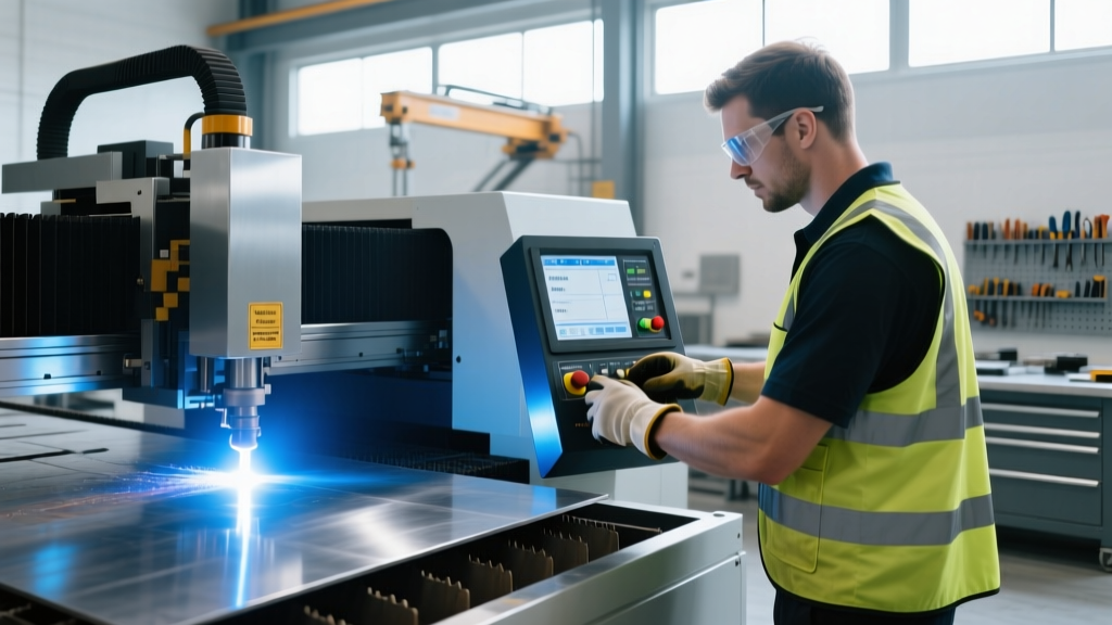
CNC plasma cutting generates significant levels of particulate matter, UV radiation, and hazardous fumes. When cutting stainless steel or high-strength low-alloy (HSLA) steels, the process generates hexavalent chromium, a known carcinogen. OSHA's guidelines on hexavalent chromium mandate a strict Permissible Exposure Limit (PEL) of 5 micrograms per cubic meter of air (µg/m³) as an 8-hour time-weighted average.
Downdraft vs. Water Table Capture
To maintain compliance and protect operator health, facilities must choose between high-velocity downdraft tables and water injection tables.
- Downdraft Tables: Require massive CFM ratings (often 4,000 to 8,000 CFM for a 5x10 table) and HEPA-grade cartridge dust collectors. Filters must be pulse-cleaned regularly, and the captured hazardous dust must be disposed of as industrial waste.
- Water Tables: Submerging the plate under 2-3 inches of water captures 95% of particulate matter and eliminates UV glare. However, water tables require strict pH management. Operators must maintain a water pH between 8.0 and 9.0 using alkaline additives to prevent the table from rusting and to inhibit anaerobic bacterial growth, which causes severe hydrogen sulfide odors.
Shift-Start Operator Checklist
- Verify plasma gas and shield gas cylinder pressures (minimum 150 PSI at the source).
- Inspect electrode hafnium pit depth; replace if exceeding 1/32'.
- Check nozzle orifice for ovality or copper slag buildup.
- Confirm THC corner-lockout and anti-dive parameters match the day's material thickness.
- Test water table pH (if applicable) and adjust to 8.5.
- Run a dry-run of the first nested part to verify pierce locations and lead-in/lead-out geometry.