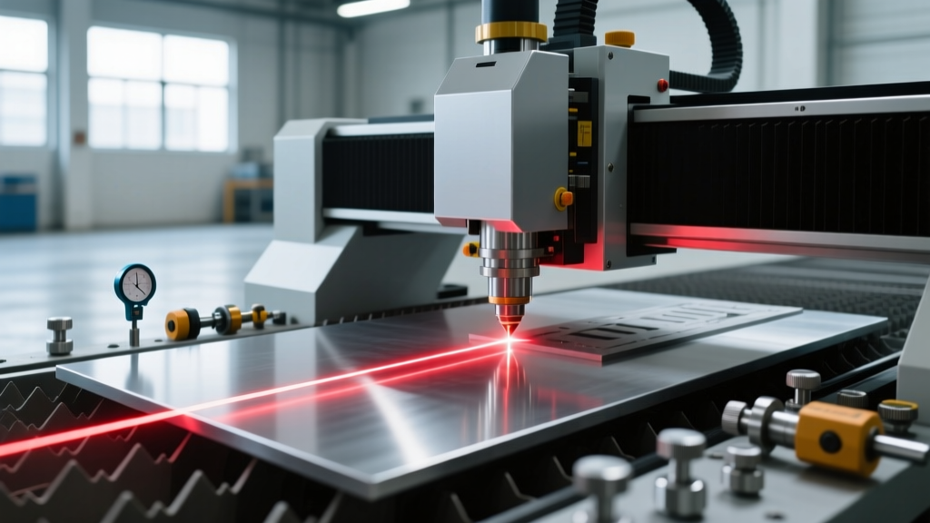
CNC Die Cutting Machine Operator Training & Setup Best Practices
Master your CNC die cutting machine with expert operator training. Learn vacuum setup, oscillating knife calibration, and material nesting best practices.
Core Competencies for Flatbed CNC Die Cutting Operations
Operating a flatbed CNC die cutting machine—such as the Zünd G3 2XL-3200 or Kongsberg C64—requires moving beyond basic CAD/CAM software knowledge. Modern digital die cutting relies on high-frequency oscillating knives, precision drag tools, and optical registration systems to process non-metallic materials ranging from 0.5mm PTFE films to 50mm EPDM rubber gaskets. Operator error in material hold-down, tool selection, or Z-axis calibration directly results in kerf deviation, delamination, and scrapped production runs. This guide outlines the technical training protocols required to maintain tolerances within ±0.1 mm in high-volume manufacturing environments.
Critical Safety & Deflection Warning: When cutting dense elastomers or aramid fibers (e.g., Kevlar), lateral blade deflection can exceed 1.5mm on deep passes. Never force a single-pass cut on materials exceeding 15mm thickness with a standard 16° blade. Utilize multi-pass step-down routines and ensure all machine guarding complies with OSHA's machine guarding standards to prevent operator injury from shattered carbide tips.Vacuum Table Zoning and Material Hold-Down Dynamics
The most common cause of dimensional inaccuracy in CNC die cutting is material shift during high-speed directional changes. Flatbed machines utilize multi-zone vacuum tables to secure materials, but operators frequently misunderstand the fluid dynamics of porous versus non-porous substrates.
Calculating CFM Requirements
A standard 4kW vacuum pump generates approximately 250 CFM (cubic feet per minute). When cutting porous materials like corrugated board or open-cell foams, air bleeds through the substrate, collapsing the vacuum pressure. Operators must employ specific mitigation strategies:
- Edge Sealing: Use 2-inch low-tack masking tape to seal the perimeter of the cutting area, forcing the vacuum to pull exclusively through the active cutting zone.
- Sacrificial Overlays: For highly porous materials, overlay a 0.5mm non-porous polyurethane film to stabilize the pressure differential.
- Zoning Protocols: Activate only the specific vacuum zones directly beneath the material footprint. Engaging the full 3200mm bed for a 500mm part drops localized suction pressure by up to 60%, guaranteeing material creep.
Tool Head Selection: Blade Geometry and Application Matrix
Selecting the correct tool head is not a matter of preference; it is dictated by the material's tensile strength, thickness, and abrasiveness. According to Zünd's official cutting technology documentation, matching the oscillation stroke rate to the material density prevents edge melting and fiber tearing.
| Tool Type | Blade Angle | Stroke Rate / RPM | Ideal Material | Max Thickness |
|---|---|---|---|---|
| Electric Oscillating Tool (EOT) | 16° | 10,000 - 18,000 spm | Vinyl, textiles, thin films | 5mm |
| Pneumatic Oscillating Tool (POT) | 26° | 6,000 - 12,000 spm | EPDM rubber, neoprene, foam | 50mm |
| Drag Knife (UCT) | 39° | N/A (Passive) | Sandwich boards, corrugated | 15mm |
| Creasing Wheel (RCT) | N/A (Blunt) | N/A | Folding carton, packaging | 2mm |
Optical Registration and Vision System Calibration
When processing pre-printed materials or die-cutting nested components based on existing fiducial marks, the machine's CCD (Charge-Coupled Device) vision system must compensate for material distortion introduced during the printing or lamination process.
- Fiducial Placement: Ensure registration marks are at least 5mm in diameter and printed in high-contrast black (CMYK 100/100/100/100). Avoid placing marks within 15mm of the material edge, as edge roll can distort the camera's focal plane.
- Lighting Calibration: Adjust the LED ring light intensity based on substrate reflectivity. Highly reflective materials (like metallized polyester) require polarized filters or diffused lighting to prevent camera washout.
- Distortion Mapping: Utilize the software's affine transformation tools to map a minimum of four registration points. For materials prone to stretching (e.g., 2mm silicone sheets), increase the point density to a 9-point grid to allow the software to calculate localized X/Y skew and dynamically adjust the cutting path.
Z-Axis Calibration and Overcut Parameters
Proper Z-axis zeroing ensures the blade penetrates the material completely without scoring the underlying sacrificial cutting mat or the machine bed. Operators must use a calibrated feeler gauge (typically 0.05mm tolerance) rather than relying on visual estimation.
"The lifespan of a polyurethane cutting mat is directly tied to Z-axis calibration. Scoring the mat by even 0.2mm creates a trench that subsequent blade passes will follow, causing severe edge chattering and premature blade dulling. Recalibrate the Z-zero after every material changeover." — Senior Manufacturing Engineer, Society of Manufacturing Engineers (SME)
Setting Overcut and Lead-Out Distances
To ensure clean weeding (removal of excess matrix material), internal and external contours require precise overcut settings. Set the overcut distance to 1.5mm for materials under 3mm thick, and scale up to 3.0mm for dense rubbers exceeding 10mm. This guarantees the blade fully intersects the starting point, preventing micro-tethers that can tear the finished gasket during matrix stripping.
Troubleshooting Decision Tree: Common Cut Quality Failures
When cut quality degrades, operators must systematically isolate the variable. Use the following diagnostic framework to resolve edge defects.
- Symptom: Frayed or Fuzzy Edges on Textiles/Aramid
- Cause: Oscillation frequency is too low, or the blade is dull.
- Fix: Increase stroke rate to maximum (18,000 spm). Replace the blade. Ensure the blade depth is set exactly to material thickness + 0.1mm.
- Symptom: Dimensional Skew (Parts are wider at the top than the bottom)
- Cause: Blade deflection due to excessive lateral drag on thick, dense materials.
- Fix: Switch to a stiffer, thicker blade shank. Reduce cutting speed by 30%. Implement a two-pass step-down routine (e.g., cut 50% depth on pass one, 100% on pass two).
- Symptom: Material Creep / Shifting Mid-Cut
- Cause: Insufficient localized vacuum pressure or dull blade pulling the material upward.
- Fix: Check vacuum pump filters for clogging. Deactivate unused bed zones. Apply edge taping to porous materials. Verify blade sharpness.
- Symptom: Incomplete Cuts at Sharp Corners
- Cause: Machine deceleration at corners reduces oscillation efficiency, or tool radius compensation is miscalculated.
- Fix: Enable 'corner dwell' or 'corner overcut' settings in the CAM software to allow the oscillating knife to clear the material at directional changes.
Preventative Maintenance Schedule for Drive and Spindle Systems
A CNC die cutting machine operates under intense vibrational stress, particularly when utilizing pneumatic oscillating tools at 12,000 strokes per minute. Neglecting mechanical maintenance leads to backlash in the X/Y gantry and ruined tolerances.
Daily Operator Tasks
- Purge the pneumatic lines of moisture using the inline desiccant dryer; water ingress into the oscillating motor will destroy the internal bearings within 40 operating hours.
- Inspect the sacrificial cutting mat for deep trenches. Rotate or flip the mat sections if localized wear exceeds 1.5mm depth.
- Clean the CCD camera lens with anhydrous isopropyl alcohol and a microfiber optic wipe to ensure accurate fiducial reading.
Bi-Annual Technician Tasks
- Re-lubricate the linear guide rails using ISO VG 68 way oil. Avoid grease, which attracts abrasive particulate from cutting composites and foams.
- Perform a ballbar test to measure circular interpolation accuracy. If backlash exceeds 0.05mm, adjust the servo motor tension and realign the helical rack and pinion drive gears.
- Replace the vacuum pump intake filters and check the carbon vanes for wear. A drop in CFM output directly correlates to increased material scrap rates.
Mastering the CNC die cutting machine requires a synthesis of material science, mechanical aptitude, and rigorous adherence to setup protocols. By standardizing vacuum zoning, respecting blade geometry limits, and implementing systematic troubleshooting, manufacturing facilities can maximize throughput while holding tight-tolerance specifications across diverse non-metallic substrates.