What Does CNC Machine Mean? CNC vs. Manual & 3D Printing Compared
Learn what does CNC machine mean in manufacturing. Compare CNC tolerances, costs, and speeds against manual milling and industrial 3D printing.
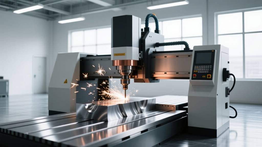
When engineers, designers, and procurement teams ask, what does CNC machine mean, they are often looking past the literal acronym to understand its practical impact on the manufacturing floor. Literally, CNC stands for Computer Numerical Control. It refers to the automated control of machining tools—such as drills, lathes, mills, and routers—by means of a computer executing a pre-programmed sequence of machine control commands. However, in modern industrial contexts, understanding CNC requires comparing it directly against its primary alternatives: traditional manual machining and industrial additive manufacturing (3D printing).
The Core Definition
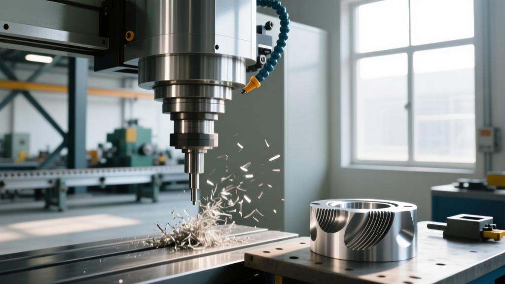
A CNC machine is a subtractive manufacturing system where a workpiece is shaped by removing material. The "Numerical Control" aspect means the toolpath is governed by coordinate geometry (X, Y, Z, and rotational axes) translated into G-code (movement) and M-code (machine functions like coolant flow and spindle activation), eliminating the need for manual hand-wheel operation.
Deconstructing the Control: G-Code, M-Code, and Axes
To truly grasp what a CNC machine does, you must understand the language it speaks. Unlike a manual mill where an operator physically turns cranks to move the table, a CNC mill uses digital servos. The CAM (Computer-Aided Manufacturing) software generates two primary types of code:
- G-Code (Geometric Code): Dictates the physical movement of the cutting tool. For example,
G01 X1.5 Y2.0 F10tells the machine to move linearly to the X and Y coordinates at a feed rate of 10 inches per minute. - M-Code (Miscellaneous Code): Controls auxiliary machine functions.
M03starts the spindle rotating clockwise, whileM08turns on the flood coolant.
Modern CNC machining centers, such as the widely utilized Haas VF-2, operate on 3 to 5 axes simultaneously. A 5-axis machine (like the Haas UMC-750) can rotate the workpiece on two additional rotational axes (A and B or B and C), allowing the cutting tool to access complex geometries, such as aerospace turbine blades, in a single setup. This multi-axis capability is the primary differentiator when comparing CNC to alternative manufacturing methods.
Process Comparison: CNC vs. Manual Milling vs. 3D Printing
Choosing a manufacturing method is rarely about which technology is universally "best"; it is about matching the process to the volume, tolerance, and material requirements. Below is a direct comparison of CNC machining, manual machining (using a standard knee mill), and industrial FDM (Fused Deposition Modeling) 3D printing.
| Feature | CNC Machining (e.g., Haas VF-2) | Manual Milling (e.g., Bridgeport Series I) | Industrial 3D Print (e.g., Markforged X7) |
|---|---|---|---|
| Base Equipment Cost | ~$65,000 - $85,000 | ~$15,000 - $22,000 | ~$115,000 - $130,000 |
| Standard Tolerance | ±0.0005" (0.0127 mm) | ±0.002" (0.05 mm) | ±0.005" (0.127 mm) |
| Setup Time | 2 to 6 hours (CAM + Fixturing) | 15 to 45 minutes | 5 to 15 minutes (Slicing + Bed Prep) |
| Surface Finish (Ra) | 1.6 μm to 3.2 μm | 3.2 μm to 6.3 μm | 15 μm to 25 μm (Layer lines visible) |
| Material Waste | High (Subtractive from billet) | High (Subtractive from billet) | Low (Additive, only support waste) |
The Break-Even Analysis: Cost Per Part at Scale
According to guidelines published by the Society of Manufacturing Engineers (SME), process selection must be driven by production volume. The high initial setup cost of CNC programming and custom fixturing makes it economically unviable for single prototypes, but unbeatable for production runs.
Scenario A: The One-Off Prototype (Volume = 1)
If you need a single aluminum 6061-T6 bracket machined to ±0.002" tolerance:
- Manual Machining: A skilled machinist can indicate the stock, manually mill the profile, and drill the holes in 2 hours. At a shop rate of $90/hour, the part costs $180.
- CNC Machining: The programmer spends 2 hours in Mastercam ($180), the setup technician spends 1.5 hours indicating the vise and loading tools ($135), and the machine runs for 20 minutes ($30). Total cost: $345.
- 3D Printing: If the part does not require metallic structural integrity, printing it in Markforged Onyx (carbon-fiber reinforced nylon) takes 10 minutes of prep and 6 hours of unattended printing. Material and machine time cost roughly $45.
Verdict: 3D printing wins for non-metal functional prototyping; manual machining wins for quick, one-off metal parts where extreme precision is not required.
Scenario B: The Production Run (Volume = 500)
When scaling to 500 identical aluminum brackets, the economics invert dramatically:
- Manual Machining: The machinist must repeat the manual setup and hand-cranking for every single part. 500 parts × 2 hours × $90/hr = $90,000. Furthermore, human fatigue introduces variance; holding ±0.002" across 500 manual setups is highly improbable.
- CNC Machining: The initial $345 setup is amortized. Once the program is proven, the cycle time drops to 12 minutes per part (using optimized toolpaths and high-pressure coolant). 500 parts × 0.2 hours × $90/hr = $9,000 in run time. Total cost: $9,345 ($18.69 per part).
- 3D Printing: FDM printing 500 parts requires massive farm management, post-processing to remove supports, and yields parts with anisotropic strength (weak along the Z-axis). Total cost hovers around $18,000.
Verdict: CNC machining is the undisputed champion for medium-to-high volume metal part production, offering a 90% cost reduction over manual methods at 500 units.
Decision Framework: Selecting Your Manufacturing Method
The NIST Manufacturing Extension Partnership (MEP) frequently advises small-to-medium manufacturers to adopt hybrid workflows rather than relying on a single technology. Use this decision matrix to route your parts correctly:
Routing Rules for Production Floors
- Is the part geometry highly complex with internal lattices or organic curves?
Route to 3D Printing (Additive). Subtractive tools cannot reach internal, non-linear cavities. - Does the part require tight press-fit tolerances (±0.0005") and high surface finish (Ra 1.6 μm)?
Route to CNC Machining. Neither manual mills nor standard FDM printers can achieve these ISO 230-2 standard tolerances consistently. - Is it a simple 2.5D bracket, shim, or spacer needed immediately for a line-down maintenance fix?
Route to Manual Machining. Bypassing the CAM programming queue saves hours of downtime. - Are you producing over 1,000 units of a complex metal part?
Look beyond CNC to Die Casting or Metal Injection Molding (MIM). While CNC is excellent for volumes up to 5,000, tooling-based processes become cheaper per-part beyond that threshold.
Frequently Asked Questions
What does CNC machine mean for material compatibility?
CNC machines are virtually material-agnostic, limited only by the rigidity of the machine casting and the available spindle torque. A rigid CNC mill can machine soft plastics (Delrin, PTFE), non-ferrous metals (Aluminum 6061, Brass 360), and hardened aerospace alloys (Titanium Ti-6Al-4V, Inconel 718). In contrast, 3D printing is strictly limited to specific polymers, resins, or specialized metal powders (in DMLS systems), while manual machines struggle with the high cutting forces required for hardened steels due to operator physical limits.
Can a CNC machine operate without a human operator?
Yes, this is the foundation of "lights-out manufacturing." Modern CNC machines equipped with pallet changers, automated tool changers (ATCs with 40+ tool pockets), and robotic part loaders can run unattended for days. However, manual machines require constant human intervention, and 3D printers require manual bed-clearing and support removal between cycles unless integrated into a highly expensive automated cell.
Why do CNC machines use G-code instead of standard CAD files?
CAD files (like STEP or IGES) contain mathematical boundary representations (B-rep) of a 3D shape. The machine's physical servo motors cannot interpret a 3D shape directly. G-code acts as the universal translator, breaking the 3D geometry down into thousands of microscopic, sequential linear and arc movements (X, Y, Z coordinates) that the machine's controller can execute in real-time, factoring in tool diameter compensation (G41/G42) and feed rates.