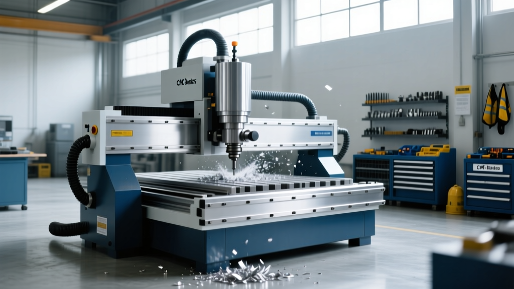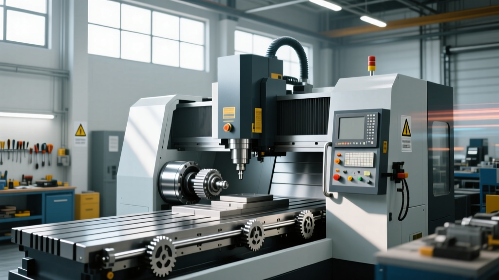
The True Meaning of CNC Machine Architecture: Troubleshooting Guide
Discover the practical meaning of CNC machine architecture. Learn to troubleshoot servo loops, spindle faults, and controller errors with expert guides.
The Literal vs. Operational Meaning of CNC Systems
When operators and students first search for the meaning of CNC machine technology, they are typically met with the literal acronym: Computer Numerical Control. However, for maintenance technicians, millwrights, and manufacturing engineers, the true meaning of a CNC machine extends far beyond automated G-code execution. Operationally, a CNC machine is a closed-loop cyber-physical system where digital commands are continuously reconciled against physical reality via high-resolution feedback loops.
Misunderstanding this architectural meaning is the root cause of 80% of misdiagnosed faults on the shop floor. When a technician views the machine merely as a "computer moving a motor," they tend to swap expensive servo drives when the actual failure is a mechanical binding issue or a degraded shielded cable. To troubleshoot effectively, you must understand the machine as an integrated loop of command, actuation, mechanics, and feedback.
Core Definition: In a troubleshooting context, the meaning of a CNC machine is a synchronized network of position loops (accurate to 0.0001 inches or 0.001 mm), velocity loops, and current loops, all operating in real-time to minimize following error.Deconstructing the Closed-Loop Feedback Architecture
Before pulling out a multimeter, you must trace the signal path. Modern industrial machining centers (such as those utilizing Fanuc 31i or Siemens Sinumerik 840D sl controllers) rely on absolute encoders and high-speed serial communication buses (like FANUC Serial Servo Bus or Siemens DRIVE-CLiQ).
The architecture flows in a continuous circle:
- 1. The Command: The interpolator generates a theoretical position trajectory.
- 2. The Drive: The servo amplifier converts low-voltage logic into high-amperage 3-phase AC power.
- 3. The Actuator: The servo motor converts electrical energy into rotational torque.
- 4. The Mechanics: Ballscrews, linear guides, and way covers translate rotation into linear axis movement.
- 5. The Feedback: The motor encoder (and often a secondary linear scale, like a Heidenhain glass scale) reads the actual position and sends it back to the controller to calculate the following error.
If an alarm triggers, the fault lies somewhere in this five-stage loop. Isolating the stage is the essence of CNC troubleshooting.
The 4-Stage Diagnostic Flow for Servo Following Errors
A "Following Error" (e.g., Fanuc Alarm 411 or Haas Alarm 102) means the physical axis is lagging behind the digital command by a value exceeding the parameter limit (typically set around 0.05mm in parameters like Fanuc PRM 1828). Here is the exact diagnostic sequence to isolate the meaning of the fault:
- Isolate the Electronics: Power down and swap the servo motor power cables (U, V, W) and feedback cables with a known-good axis (e.g., swap X and Y). If the alarm follows the cable/drive, the fault is electronic (failed IGBT in the drive or broken encoder wire).
- Test the Mechanics (Unloaded): Disconnect the ballscrew from the servo motor (remove the coupling). Command the motor to spin via the controller's manual tuning screen. If it spins smoothly, the motor and drive are healthy.
- Measure Mechanical Bind: Attach a dial indicator to the axis and use a torque wrench on the ballscrew. A healthy 40mm ballscrew should require less than 2-3 Nm of breakaway torque. If torque spikes at a specific point in the travel, you have a mechanical bind (damaged recirculating balls, misaligned way covers, or lack of lubrication).
- Check the Feedback Resolution: Use an oscilloscope to read the encoder A/B/Z phase signals. A degraded cable will show voltage drops below the 5V TTL threshold, causing the controller to miscalculate position.
Translating Controller Alarms to Physical Failures
Controller alarms are cryptic by design, protecting proprietary logic. Understanding the operational meaning of these codes requires translating them into physical actions. Below is a diagnostic matrix for common industrial alarms.
| Controller / Alarm Code | Displayed Message | Physical Root Cause (The True Meaning) | Diagnostic Action & Tooling |
|---|---|---|---|
| Fanuc 414 | Servo Alarm: X Axis Detect | Abnormal current draw in the servo motor; often caused by mechanical overload or shorted motor windings. | Use a Megohmmeter (Megger) at 500V DC to test motor winding insulation to ground. Must read >100MΩ. |
| Haas 114 | X Axis Motor Overload | The servo drive's internal thermal model estimates the motor is overheating, or the physical brake has not fully released. | Verify 24V DC is reaching the axis brake coil. Check for collapsed way lube lines causing dry sliding friction. |
| Siemens 25050 | Axis Contouring Error | The actual velocity deviated from the setpoint velocity beyond the tolerance band during interpolation. | Check the mechanical backlash via a Renishaw Ballbar test. Inspect the motor-to-ballscrew coupling for shear pin failure. |
| Heidenhain 103 | Positioning Error | Discrepancy between the rotary motor encoder and the linear glass scale exceeding the machine parameter limit. | Clean the glass scale reader head with isopropyl alcohol. Check for coolant intrusion in the scale housing. |
Spindle Drive Faults: Mechanical vs. Electronic
The spindle is the heart of the CNC machine, and its faults often blur the line between mechanical wear and electronic failure. A frequent issue is the failure of the M19 (Spindle Orient) command, which halts tool changes and causes catastrophic crashes.
When an M19 command fails to lock the spindle at the precise 0-degree orientation, technicians often immediately suspect the spindle drive. However, in belt-driven spindles (like those on standard VMCs), the true meaning of the fault is usually mechanical slip or Z-phase encoder degradation.
Critical Troubleshooting Warning: Never attempt to adjust the spindle drive's orientation offset parameters to compensate for a slipping belt. If the belt slips under load, the tool will pull out of the toolholder, destroying the workpiece and potentially damaging the spindle taper. Always verify belt tension using a sonic tension meter (target frequency varies by belt length, typically 40-60 Hz for standard VMC poly-V belts) before touching software parameters.Diagnostic Steps for Spindle Orientation Faults:
- Step 1: Command M19 and mark the spindle nose with a dykem marker. Cycle the command 10 times. If the mark scatters across a 5-degree arc, the spindle encoder's one-turn (Z-phase) signal is degrading, or the belt is loose.
- Step 2: If the mark lands in the exact same wrong position every time, the mechanical coupling between the encoder and the spindle shaft has slipped. Re-align using the manufacturer's physical pin or laser alignment tool.
- Step 3: Check the spindle cooling system. Overheating causes thermal expansion of the rotor, altering the air gap in the motor and changing the electrical timing, which can result in orientation drift.
The Hidden Meaning of Grounding and Noise
In the context of CNC repair, "electrical noise" is not a vague concept; it is measurable electromagnetic interference (EMI) that corrupts the 5-volt feedback signals traveling from the encoders to the controller. According to guidelines published by AMT - The Association For Manufacturing Technology, improper grounding is responsible for a significant percentage of "ghost" alarms—faults that appear randomly and disappear when a technician arrives.
CNC machines require a dedicated, clean earth ground. The resistance from the machine's ground bus bar to the physical earth ground rod must be less than 5 ohms. If a facility uses a "daisy-chain" grounding method (linking the CNC machine's ground to a welder or a large air compressor), the massive inductive spikes from those peripheral machines will travel back up the ground wire and corrupt the CNC's sensitive logic boards.
Actionable Fix: Install an isolated ground rod specifically for the CNC cell. Use a Fluke 1630-2 FC Earth Ground Clamp Meter to measure the ground loop resistance without disconnecting the system. If resistance exceeds 5 ohms, treat the earth with conductive enhancement material (like bentonite clay) to lower the soil resistivity.
Preventative Calibration to ISO 230 Standards
Understanding the meaning of CNC machine architecture ultimately leads to proactive maintenance rather than reactive repair. The global benchmark for machine tool accuracy is the ISO 230-1 Test Code for Machine Tools, which dictates how geometric accuracy, thermal effects, and positioning errors must be measured and compensated.
Modern CNC systems utilize bidirectional pitch error compensation and backlash compensation tables. Over time, as ballscrews wear, these tables become obsolete, leading to out-of-tolerance parts even when the machine reports no alarms.
"The shift toward smart manufacturing requires machines to not only execute code but to monitor their own physical degradation. Integrating real-time spindle load monitoring and servo current tracking allows facilities to predict mechanical failures before they result in scrapped parts." — NIST Smart Connected Manufacturing Division
To maintain ISO-level accuracy, implement the following quarterly diagnostic matrix:
- Ballbar Testing (ISO 230-4): Run a circular interpolation test using a telescoping ballbar (e.g., Renishaw QC20-W). Look for stick-slip friction (indicates way lube failure) and reversal spikes (indicates backlash compensation needs updating).
- Thermal Growth Analysis (ISO 230-3): Run a 4-hour warm-up cycle and measure Z-axis growth using a dial indicator. Modern controllers allow you to input thermal compensation variables to automatically adjust the Z-axis offset as the cast iron expands.
- Servo Tuning Verification: Use the controller's built-in Bode plot or frequency response analysis tool to ensure the position loop gain remains stable. A dropping phase margin indicates mechanical resonance developing in the axis structure.
Summary: Shifting from Parts Swapping to System Diagnostics
Grasping the true meaning of CNC machine systems transforms a technician from a "parts swapper" into a diagnostic engineer. By viewing the machine as a continuous closed-loop architecture, respecting the physical realities of mechanical torque and electrical grounding, and utilizing standardized ISO diagnostic frameworks, you can drastically reduce mean-time-to-repair (MTTR) and eliminate chronic, unexplained machine faults.