How Does CNC Machining Work? Axis, Spindle & G-Code Specs
Explore how CNC machining works technically. We break down servo feedback loops, G-code interpolation, spindle dynamics, and controller architecture.
The Cyber-Physical Loop: Beyond Basic Automation
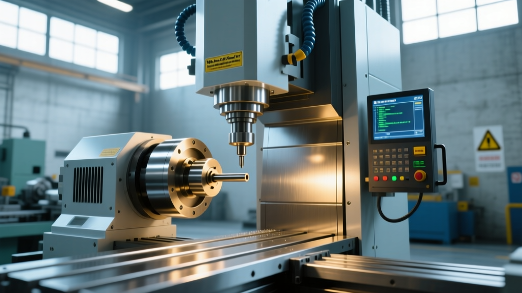
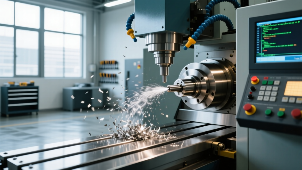
To understand how does CNC machining work at an industrial level, you must look past the basic definition of "computer-controlled cutting." Modern CNC (Computer Numerical Control) systems are high-speed, closed-loop cyber-physical systems. They translate mathematical vectors into electromechanical motion with sub-micron precision. The process relies on a continuous feedback loop between a central processor, servo amplifiers, and high-resolution encoders, executing thousands of calculations per millisecond to maintain exact toolpath trajectories under heavy cutting loads.
Technical Baseline: A standard 3-axis vertical machining center (VMC) operating at 10,000 RPM and 300 IPM (inches per minute) requires the controller to process approximately 5,000 to 10,000 positional feedback updates per second just to maintain a linear tolerance of ±0.0002 inches.Controller Architecture and Look-Ahead Processing
The CNC controller is the brain of the machine. Modern platforms, such as the Siemens SINUMERIK ONE or Fanuc Series 31i, do not merely read G-code line-by-line. They utilize advanced look-ahead algorithms to anticipate changes in toolpath geometry.
Block Processing and Kinematic Smoothing
When machining complex 3D contours, CAM software generates thousands of tiny linear segments (G01 moves). If the controller processed these sequentially without foresight, the machine would decelerate to a near-stop at every micro-junction, causing dwell marks and tool wear. Advanced controllers buffer 200 to 1,000+ blocks of code in advance. By analyzing the upcoming vectors, the controller calculates the optimal deceleration and acceleration curves, maintaining a constant feed rate through corners while respecting the machine's physical jerk limits (the rate of change of acceleration, measured in m/s³).
G-Code Interpolation and Axis Kinematics
G-code is the standardized language governing CNC motion, originally rooted in the NIST RS274NGC standard. However, the physical execution of commands like G02 (clockwise arc) or G03 (counterclockwise arc) requires complex real-time interpolation.
- Linear Interpolation (G01): The controller calculates the exact ratio of power required by the X, Y, and Z servo motors to arrive at the target coordinate simultaneously, forming a perfectly straight line.
- Circular Interpolation (G02/G03): The controller continuously recalculates the sine and cosine values for the X and Y axes in real-time to generate a smooth arc, adjusting for mechanical backlash and ball screw pitch errors via pitch error compensation tables.
- Helical Interpolation: Simultaneous circular movement in the X-Y plane combined with linear movement in the Z-axis, heavily utilized for thread milling and deep hole boring.
Nano-Interpolation Specifications
High-precision mold-making machines utilize nano-interpolation, where the internal mathematical resolution operates at 0.0001 mm (0.1 microns). This ensures that even when cutting microscopic radii, the servo motors receive a continuous stream of positional data, eliminating the "stair-stepping" effect common in lower-tier controllers.
Servo Motors and Closed-Loop Feedback
The physical movement of a CNC machine is driven by AC synchronous servo motors. Unlike stepper motors, which operate in open-loop systems and can lose steps under load, CNC servos rely on closed-loop feedback to guarantee positional accuracy.
| Component | Standard VMC Spec | High-Speed/Micron Spec |
|---|---|---|
| Encoder Resolution | 17-bit (131,072 pulses/rev) | 24-bit (16,777,216 pulses/rev) |
| Feedback Type | Incremental (requires homing) | Absolute (battery-backed) |
| Scale Feedback | None (relies on motor encoder) | Linear glass scales (0.001mm) |
| PID Loop Tuning | Standard factory auto-tune | Custom frequency response tuning |
In high-end machines, dual-feedback systems are employed. The motor's internal encoder tracks rotor position, while separate linear glass scales mounted directly to the machine's cast iron frame measure the actual position of the table. This dual-loop setup completely eliminates errors caused by ball screw thermal expansion or mechanical wear.
Spindle Dynamics and Tool Engagement
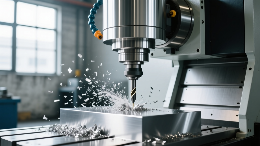
The spindle is the heart of the material removal process. Understanding how does CNC machining work requires analyzing the spindle drive technology. Modern CNC machines utilize flux vector drives rather than standard Variable Frequency Drives (VFDs). Vector drives independently control the magnetic flux and torque-producing current of the spindle motor, allowing the machine to maintain 100% rated torque even at very low RPMs for rigid tapping or large-diameter face milling.
Thermal Growth and Runout Tolerances
As a spindle accelerates to 12,000 or 20,000 RPM, friction in the bearings generates immense heat. Uncompensated, this thermal growth can push the Z-axis downward by 30 to 50 microns over the first two hours of operation. To combat this, precision machines employ spindle chillers that circulate temperature-controlled oil (maintained at exactly 20°C ± 0.1°C) through the spindle housing. Furthermore, high-speed spindles utilize Silicon Nitride (Si3N4) ceramic hybrid bearings, which run cooler, require less lubrication, and maintain a radial runout tolerance of less than 2 microns at the tool flange.
Expert Insight: When selecting tooling for high-speed CNC operations, the toolholder is just as critical as the machine. According to Sandvik Coromant's machining guidelines, utilizing hydraulic or shrink-fit toolholders reduces runout to under 3 microns, drastically improving tool life and surface finish compared to standard ER collets.
Real-World Execution: A Milling Cycle Microsecond Breakdown
To synthesize these components, here is the exact chronological sequence of events when a CNC machine executes a single G01 cutting move under load:
- T+0.000 ms (Code Read): The controller reads the G01 block, extracts the target X/Y/Z coordinates, and applies tool length and cutter radius compensation offsets.
- T+0.002 ms (Path Generation): The interpolator calculates the trajectory, breaking the move into micro-segments based on the programmed feed rate and machine acceleration limits.
- T+0.005 ms (Signal Output): The controller sends analog voltage or digital pulse commands to the X, Y, and Z servo amplifiers.
- T+0.010 ms (Electromagnetic Engagement): The amplifiers deliver precisely phased 3-phase AC power to the servo motors, generating magnetic fields that rotate the rotors.
- T+0.050 ms (Physical Motion & Feedback): The ball screws translate rotational force into linear motion. Simultaneously, the encoders send positional data back to the amplifier. If cutting forces push the tool 0.001mm off path, the PID loop instantly detects the following error and increases current to the motor to correct the deviation.
- T+Continuous (Spindle Load Monitoring): The spindle vector drive monitors torque. If the tool engages a hard spot in the casting, the drive increases current to maintain the exact programmed RPM, preventing stalling or tool breakage.
Summary of Technical Realities
CNC machining is not simply automated cutting; it is a rigorous exercise in real-time computational physics and electromechanical control. From the nanometer resolution of the interpolation algorithms to the thermal management of ceramic spindle bearings, every subsystem must operate in perfect synchronization. Understanding these technical specifications allows machinists and engineers to push the boundaries of feed rates, optimize toolpaths, and achieve tolerances that were considered impossible a decade ago.