How Does a CNC Machine Work? Mapping Parts to Maintenance Schedules
Learn how a CNC machine works mechanically and map each moving component to specific preventative maintenance schedules, greases, and service intervals.
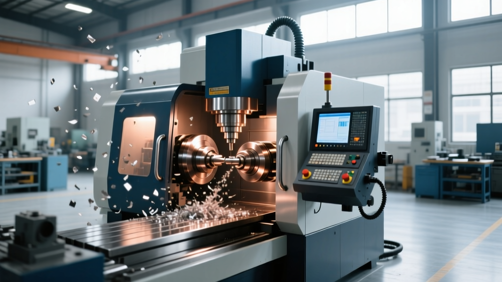
Asking how does a cnc machine work usually yields answers about CAD/CAM software, G-code, and controller logic. However, from a maintenance and reliability engineering perspective, understanding how a CNC machine works requires a deep dive into its physical kinematics, tribology (friction and lubrication), and electromechanical feedback loops. Every physical movement inside a vertical machining center (VMC) or CNC lathe generates heat, wear, and particulate contamination. By mapping the mechanical function of each subsystem to its specific failure mode, facilities can transition from reactive breakdown repairs to precision-driven preventative maintenance (PM) schedules.
The Core Kinematics: How Motion Dictates Service Intervals
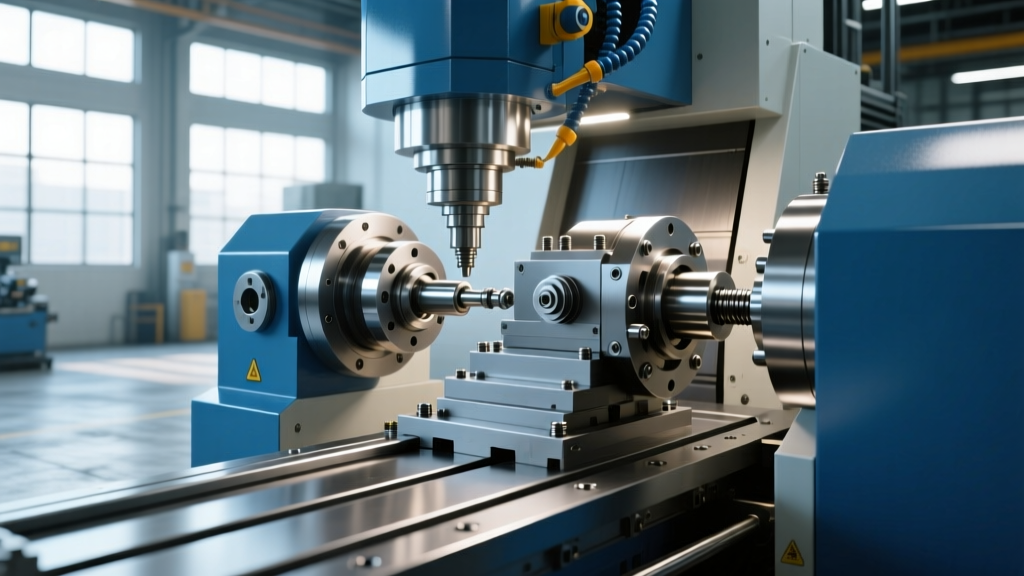
A CNC machine translates rotational motor torque into precise linear motion. The servo motor turns a ballscrew, which drives a nut attached to the machine casting or saddle. This assembly rides on linear guideways (LM guides) or hardened box ways. The fundamental challenge in this mechanical chain is managing thermal growth and backlash. As the ballscrew rotates at high RPMs (often exceeding 3,000 RPM in rapid traverse), friction generates heat, causing the screw to expand. If the maintenance schedule ignores the degradation of the ballscrew support bearings or the depletion of the lubricant film, the machine will suffer from positioning errors that violate ISO 230-2 standards for machine tool accuracy.
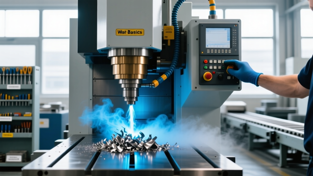
⚠️ WARNING: Way Cover DegradationThe telescopic steel way covers are the first line of defense for your linear guides. If a way cover wiper seal fails and allows abrasive cast iron or aluminum swarf to pack inside the LM guide carriage, the recirculating ball bearings will spall. Replacing a single THK or Hiwin carriage block costs between $350 and $800, not including the 4-6 hours of downtime and laser calibration required. Inspect way cover bellows and wiper seals every 500 operating hours.
Spindle Mechanics and Bearing Preload Maintenance
The spindle is the heart of the machine's material removal capability. Most modern CNC milling spindles utilize paired super-precision angular contact ball bearings arranged in a back-to-back (DB) or face-to-face (DF) configuration to handle both radial and axial cutting forces. These bearings are preloaded at the factory using precision ground spacers to eliminate internal clearance, ensuring high rigidity and rotational accuracy.
Understanding how the spindle works means understanding its lubrication method. High-torque, lower-RPM spindles (e.g., 8,000 RPM belt-driven) often use grease-packed bearings. High-speed spindles (12,000 to 20,000+ RPM) rely on oil-air lubrication systems that meter microscopic droplets of oil (such as Kluber Isoflex NBU 15 or specialized spindle oils) into the bearing raceway via compressed air. If the oil-air metering unit's filter clogs, or if the air pressure drops below the required 4-6 bar, the bearing will run dry, leading to catastrophic thermal seizure in under 15 minutes.
- Grease-Packed Spindles: Require a break-in procedure after replacement. Bearings typically last 8,000 to 12,000 hours before grease base oil separation occurs, necessitating a complete spindle rebuild (costing $4,000 to $15,000+).
- Oil-Air Spindles: Require monthly verification of the oil drip rate at the spindle manifold and annual replacement of the desiccant in the compressed air supply line to prevent moisture-induced bearing corrosion.
Ballscrew and Linear Guide Tribology
Linear motion components require a continuous film of lubricant to prevent metal-on-metal contact. The specific type of lubricant depends on the machine's design. Machines with centralized automatic lube systems pump way oil (typically an ISO VG 68 tackified oil like Mobil Vactra Oil No. 2) through metering units to the LM guides and ballscrews. The 'tackifier' additive prevents the oil from being thrown off by centrifugal force during high-speed rapids.
Conversely, some machines utilize sealed, grease-lubricated linear guides. According to NSK's machine tool bearing and linear motion guidelines, over-greasing a sealed carriage block is just as detrimental as under-greasing. Excess grease increases rolling resistance, generating heat and causing the carriage seals to blow out, allowing coolant ingress.
CNC Component Maintenance Matrix
| Mechanical Component | Primary Function | Common Failure Mode | Preventative Maintenance Action | Interval |
|---|---|---|---|---|
| Ballscrew Support Bearings | Absorb axial thrust during cutting | Preload loss, axial play, backlash | Check X/Y/Z axis backlash via dial indicator; re-tension if >0.0005" | 6 Months |
| ATC Cam Box (Tool Changer) | Coordinates arm swing and Z-axis extraction | Grease degradation, arm crash, cam follower wear | Drain and refill with Mobilgrease XHP 222; inspect roller followers | 2,000 Hours |
| Absolute Servo Encoders | Retain machine home position on power loss | Battery voltage drop, loss of absolute origin | Replace Panasonic BR-2/3AGCT4A batteries (MUST be done with power ON) | 12 Months |
| Spindle Drawbar / Belleville Springs | Clamp toolholder taper with 1,500+ lbs of force | Spring fatigue, tool pull-out during heavy milling | Measure pull-stud retention force using a calibrated drawbar force gauge | 6 Months |
| Coolant Concentration & Tramp Oil | Lubricate cutting zone, flush chips | Bacterial growth, way cover seal degradation | Test with refractometer (maintain 8-10%); run tramp oil skimmer daily | Weekly / Daily |
Servo Feedback Loops and ATC Cam Mechanics
Understanding how a CNC machine works also requires understanding the Automatic Tool Changer (ATC). The ATC is a purely mechanical sequence driven by a single servo or induction motor connected to a complex cam box (often utilizing a Geneva mechanism or a globoidal cam). This cam translates continuous rotation into the precise, timed sequence of arm rotation, Z-axis plunge, and tool extraction.
ATC Cam Box Grease Specifications
The cam box is bathed in grease to dampen the shock loads of high-speed tool exchanges (which can occur in under 1.5 seconds). Over time, the mechanical shearing action breaks down the grease's thickener structure, turning it into a liquid that leaks past the output shaft seals. Once the grease level drops, the cam followers strike the hardened cam track without a protective hydrodynamic film, resulting in pitting. Maintenance schedules must mandate a complete cam box fluid exchange every 2,000 to 3,000 hours using the exact OEM-specified NLGI Grade 2 lithium complex grease.
"The most overlooked maintenance task on a VMC is the drawbar force check. A machine might cut aluminum perfectly with 800 lbs of retention force, but the moment you run a 2-inch face mill in steel, the tool holder will vibrate, destroying the spindle taper and the tool. Always verify retention force meets the OEM spec—usually between 1,500 and 2,500 lbs—during bi-annual PMs."
Thermal Management and Electrical Cabinet Cooling
The electrical cabinet houses the servo drives, spindle drive, and PLC. These components generate immense heat. To maintain the internal cabinet temperature at a stable 95°F (35°C), machines use closed-loop air conditioners or heat exchangers. If the cabinet filters become clogged with shop dust, or if the AC compressor fails, the cabinet temperature can easily exceed 120°F (49°C). This thermal stress drastically reduces the lifespan of the electrolytic capacitors inside the servo drives, leading to sudden drive faults and machine downtime. Cleaning or replacing the cabinet intake filters must be a strict monthly protocol.
FAQ: Troubleshooting Mechanical Drift
Why is my CNC machine losing zero return position overnight?
If your machine loses its home position after being powered off, the absolute encoder batteries in the servo motors are likely depleted. However, if the batteries are new and the issue persists, inspect the motor-to-ballscrew coupling. A loose or cracked elastomeric coupling will cause rotational slip, meaning the motor returns to its exact electrical zero, but the ballscrew is physically offset by a few thousandths of an inch.
How do I know if my way lube system is actually working?
Do not rely solely on the pressure switch on the lube pump. A clogged metering unit can cause pressure to build up in the main line, satisfying the pressure switch and sending an 'OK' signal to the controller, while the actual LM guide receives zero oil. Visually verify that oil is weeping from the way cover wipers on all axes after a manual lube cycle, and check the reservoir drop rate against the machine's calculated volume requirements.