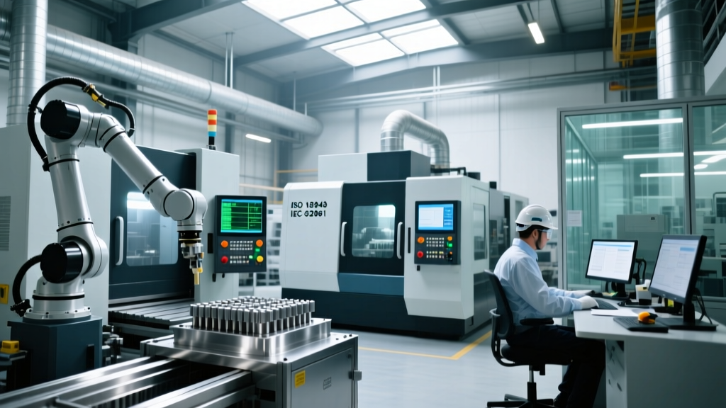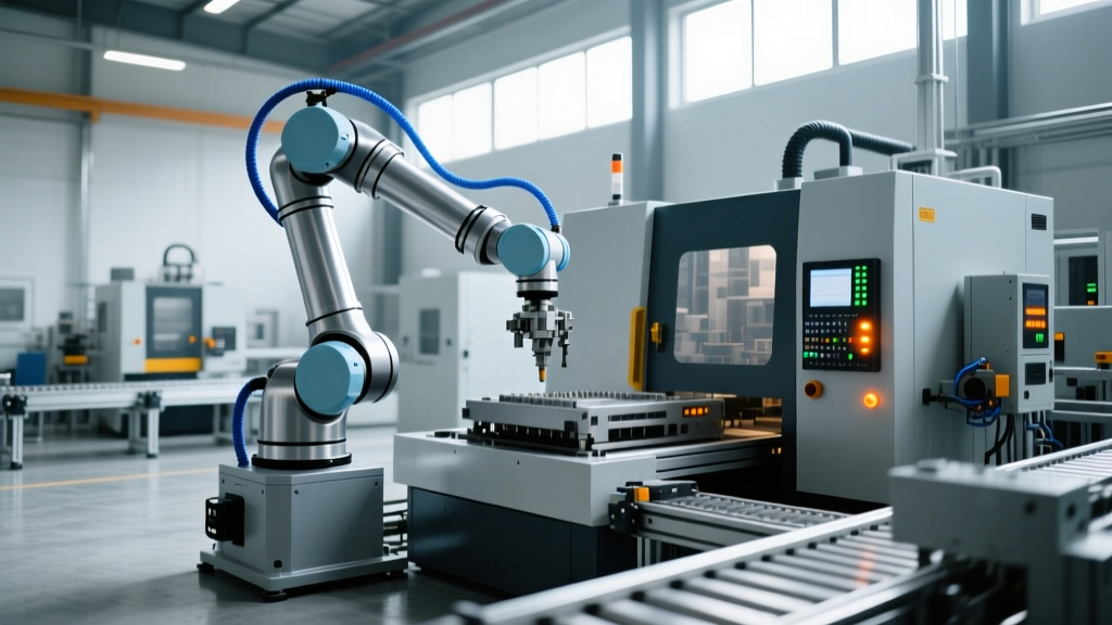
How Automation Equipment Manufacturers Engineer Robotic Cell Specs
Explore the technical specifications, PLC architectures, and kinematic tolerances that define tier-1 automation equipment manufacturers.
The Engineering Divide: OEM Specifications vs. Integrator Reality
The gap between a conceptual 3D CAD model and a deployed, high-throughput robotic cell is bridged by rigorous technical specifications. Tier-1 automation equipment manufacturers (OEMs like FANUC, KUKA, Siemens, and Rockwell Automation) do not merely assemble off-the-shelf components; they engineer deterministic kinematic chains, real-time control architectures, and fail-safe thermal management systems. For procurement engineers and system integrators, understanding how these manufacturers derive their technical specifications is critical to avoiding costly cycle-time bottlenecks and premature mechanical failures.
Unlike standard integrators who rely on brochure-level data, top-tier automation equipment manufacturers validate their systems against strict international standards, calculating non-linear error compensation and microsecond-level network jitter. This guide deconstructs the technical specifications and operational mechanics that define modern industrial robotic cells.
Kinematic Chain Tolerances: Accuracy vs. Repeatability
A common failure mode in automated welding and precision dispensing cells is the confusion between robot repeatability and absolute accuracy. Automation equipment manufacturers define these metrics strictly according to ISO 9283:1998, which outlines performance criteria and test methods for manipulating industrial robots.
Repeatability (RP)
Repeatability is the robot's ability to return to the exact same taught position over multiple cycles. A standard FANUC LR Mate 200iD/7L boasts a repeatability of ±0.01mm. This is achieved through high-resolution absolute encoders (typically 17-bit or higher, yielding 131,072 pulses per revolution) and harmonic drive gearboxes with near-zero backlash.
Absolute Accuracy (AP)
Absolute accuracy measures how close the robot's end-effector gets to a mathematically programmed coordinate in 3D space. Out-of-the-box, mechanical tolerances in gear meshing and link casting can result in absolute errors of ±0.15mm to ±0.50mm. To combat this, manufacturers engineer software-based kinematic compensation packages (such as FANUC's iRCalibration or KUKA's RoboTeam). By using external laser trackers (e.g., API Radian) to map the Denavit-Hartenberg (DH) parameters of the specific physical arm, OEMs reduce absolute accuracy errors down to ±0.03mm. Expect to pay a premium of $4,500 to $6,000 per robot for this factory-level calibration.
Engineering Insight: Never specify a robot for precision machining or laser cutting based solely on repeatability. If the application requires the robot to follow a CAD-generated path without manual teaching points, absolute accuracy calibration is a mandatory line item in the OEM specification sheet.Control Layer Architecture: PROFINET IRT vs. EtherNet/IP
The central nervous system of any automated cell is the Programmable Logic Controller (PLC) and its motion bus. Automation equipment manufacturers design their control ecosystems around specific industrial Ethernet protocols, which dictate how the PLC communicates with servo drives and I/O modules. The two dominant architectures are Siemens' PROFINET IRT (Isochronous Real-Time) and Rockwell Automation's EtherNet/IP with CIP Sync.
| Specification | Siemens SIMATIC S7-1500 (CPU 1516-3 PN/DP) | Rockwell ControlLogix 5580 (5580E) |
|---|---|---|
| Work Memory | 1.5 MB (Program) / 5 MB (Data) | 20 Mbit User Memory |
| Primary Motion Protocol | PROFINET IRT | EtherNet/IP (CIP Motion/Sync) |
| Minimum Cycle Time | 250 µs (Isochronous mode) | 1 ms (Standard CIP Sync) |
| Jitter Tolerance | < 1 µs (Hardware ASIC-based) | < 10 µs (Software/Hardware hybrid) |
| Typical Cell Hardware Cost | $18,000 - $24,000 | $22,000 - $28,000 |
How PROFINET IRT Achieves Microsecond Determinism
Standard TCP/IP Ethernet is non-deterministic, meaning packet delivery times fluctuate based on network traffic. According to the EtherCAT Technology Group and similar protocol bodies, standard industrial Ethernet handles this via store-and-forward switching. PROFINET IRT bypasses this by reserving a specific bandwidth slice (up to 50%) exclusively for real-time motion control data. The Siemens S7-1500 utilizes a dedicated ASIC (Application-Specific Integrated Circuit) on its network interface to process IRT telegrams in hardware, ensuring a jitter of less than 1 microsecond. This is mandatory for multi-axis coordinated motion, such as a 6-axis robot tracking a moving conveyor belt.
Servo Motor Thermal Derating & MTBF Calculations
Automation equipment manufacturers do not rate servo motors based on peak torque alone; they calculate continuous stall torque under specific thermal conditions. A critical specification often overlooked by integrators is the thermal time constant and ambient temperature derating curve.
For example, a Yaskawa Sigma-7 series servo motor (e.g., SGMGV-09A) might be rated for 3000 RPM continuous operation and 8.3 Nm of continuous torque at an ambient temperature of 20°C. However, if the robotic cell is deployed in a foundry or a hot climate where the ambient temperature inside the control cabinet reaches 45°C, the motor's continuous torque must be derated by approximately 20% to prevent the stator windings from exceeding their Class F insulation limit (155°C).
Warning: Failing to apply thermal derating factors in the OEM specification phase will result in the servo drives tripping on 'Overload' (Alarm A.710) during peak summer months, drastically reducing the cell's Mean Time Between Failures (MTBF).
Safety PLC Architectures: SIL3 and Performance Level 'e'
Modern automation equipment manufacturers integrate safety directly into the motion bus rather than relying on hardwired safety relays. To achieve ISO 13849-1 Performance Level 'e' (PL e) and IEC 62061 Safety Integrity Level 3 (SIL3), control systems utilize dual-channel redundant processing.
- Safe Torque Off (STO): The primary safety function, executed at the drive level. When triggered by the Safety PLC, the STO circuit physically removes power from the servo's IGBT inverter bridge. Reaction times are typically < 10ms.
- Safe Speed Monitor (SSM): Allows the robot to operate at a reduced, safe speed (e.g., 250 mm/s) when a human operator enters a collaborative zone, monitored via dual-redundant encoder feedback.
- Cross-Fault Detection: The Safety PLC continuously compares the logic states of Channel A and Channel B. If a discrepancy lasts longer than the configured discrepancy time (usually 100ms to 500ms), the system forces a safe state.
Procurement Validation Framework for Engineers
When sourcing from automation equipment manufacturers, engineering teams must validate technical claims against real-world physics. Use this 4-step framework during the design review phase:
- Demand ISO 9283 Test Certificates: Do not accept brochure specifications for payload and reach. Require the manufacturer to provide the specific ISO 9283 test certificate for the exact serial number or batch being delivered, verifying both repeatability and path accuracy.
- Audit the Cable Dress Package (CDP) Interference: A robot may have a 2000mm reach on paper, but a bulky external CDP for welding torches or vision cameras can reduce the effective working envelope by 15% due to joint limit interference. Require a 3D sweep analysis with the exact CDP model included.
- Verify PLC Scan Times Under Full I/O Load: A PLC might boast a 1ms scan time with an empty rack. Require the OEM to simulate the program with the maximum configured I/O count and motion axes active to prove the scan time remains within the required 5ms to 10ms threshold for high-speed sorting applications.
- Calculate True Cycle Time with Inertia: Payload limits (e.g., 7kg) assume the center of gravity (CG) is perfectly aligned with the tool flange. If your end-effector has a 50mm CG offset, the moment of inertia increases exponentially. Force the manufacturer to run a dynamic simulation using your exact payload geometry to verify the servo motors will not trigger inertia alarms during high-acceleration moves.
By enforcing these technical specifications and understanding the underlying mechanics of how tier-1 automation equipment manufacturers engineer their systems, facilities can deploy robotic cells that meet rigorous cycle times, maintain micron-level precision, and operate reliably for decades. For further reading on robotic safety and integration standards, refer to the guidelines published by the Association for Advancing Automation (A3).