Workholding Safety Compliance: Machining the Hair Braiding Tool Machine
Explore OSHA and ISO safety compliance for vises, chucks, and fixtures when machining precision parts for the automated hair braiding tool machine.
The Intersection of Micro-Precision and Workholding Hazards
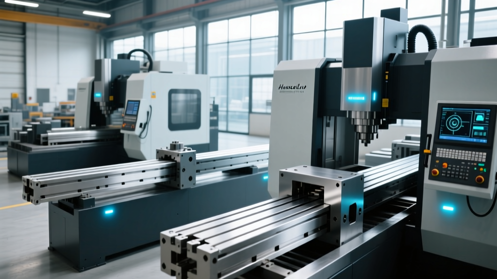
Manufacturing the automated hair braiding tool machine requires producing micro-precision components such as ceramic tensioning guides, high-speed rotary hooks, and complex cam tracks. These parts are typically machined on Swiss-type lathes and 5-axis vertical machining centers operating at spindle speeds exceeding 12,000 RPM. At these velocities, the workholding systems—specifically collet chucks, hydraulic vises, and custom milled fixtures—are subjected to extreme centrifugal forces and harmonic vibrations. A failure in workholding integrity does not merely result in a scrapped part; it creates a lethal projectile hazard. Compliance with OSHA 29 CFR 1910.212 and ANSI B11.8 standards is not optional, yet many machine shops overlook the specific physics of micro-component clamping when setting up production runs for cosmetic and textile automation equipment.
⚠️ CRITICAL SAFETY WARNING: When machining the small-diameter rotary hooks for a hair braiding tool machine, standard ER collet nuts can loosen due to high-frequency harmonic chatter. Always use a calibrated torque wrench (e.g., set to 100 Nm for ER32 collets) and apply a secondary mechanical retention ring. Never rely on hand-tightening for operations exceeding 6,000 RPM.Centrifugal Force Degradation in Collet Chucks
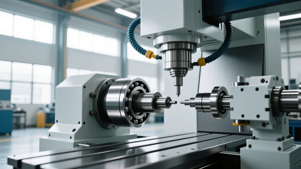
The most pervasive hazard in turning operations for braiding machine components is the loss of clamping force due to centrifugal expansion. As a standard spring collet spins, the mass of the collet segments and the internal spring mechanism push outward against the chuck body. According to data published by chuck manufacturers like SMW-Autoblok and Forkardt, a standard power chuck can lose up to 40% of its static clamping force when operating at 8,000 RPM.
For the hair braiding tool machine, the rotary hooks are often turned from 303 stainless steel or 6061-T6 aluminum at high speeds to achieve a mirror finish without secondary grinding. If the workholding system relies on standard wedge-type chucks without centrifugal compensation, the part will slip or eject. To maintain OSHA machine guarding compliance, shops must utilize counter-centrifugal chucks. These specialized workholding devices incorporate counterweights that move inward as spindle speed increases, effectively pushing the chuck jaws tighter onto the workpiece. When sourcing chucks for this application, verify the manufacturer's RPM-to-clamping-force decay chart and ensure the operational RPM falls within the green safety zone of the graph.
Interlocking Guard Mandates and ANSI B11.8
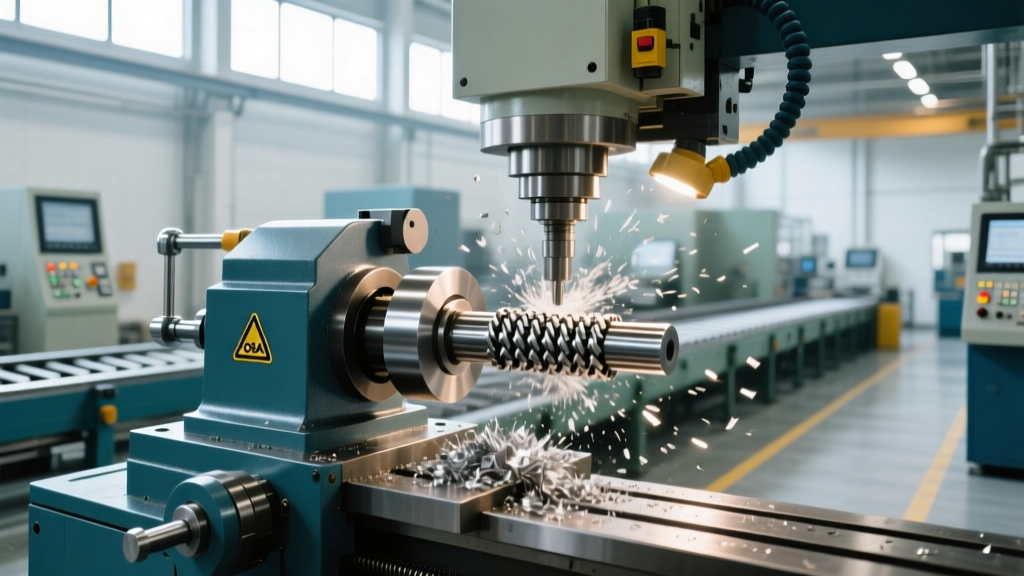
ANSI B11.8 specifically governs safety requirements for lathes and turning centers. When machining the intricate cam profiles that drive the braiding mechanism of the hair braiding tool machine, operators frequently need to access the chuck to swap out custom soft jaws or clear chip nests. This creates a severe exposure risk to rotating workholding elements.
"Machine guards must be interlocked with the machine control system so that the machine cycle cannot be initiated unless the guard is closed, and the machine must stop if the guard is opened during operation." — ANSI B11.8 Safety Standard for Lathes
To achieve compliance, shops must install chuck guards equipped with trapped-key interlocks or RFID safety switches, such as the Allen-Bradley Guardmaster 440N-Z21S. These switches prevent the spindle from engaging if the polycarbonate shield is not fully seated. Furthermore, the guard material must be rated for impact resistance; standard acrylic shatters under the impact of a ejected steel cam track. Polycarbonate (Lexan) with a minimum thickness of 0.375 inches is required to contain a 2-pound workpiece ejecting at 4,000 RPM surface speed.
Workholding Selection Matrix for Braiding Machine Components
| Workholding Type | Typical Braiding Machine Part | Max Safe RPM / PSI | Primary Safety Hazard | Required Compliance Control |
|---|---|---|---|---|
| Standard ER Collet Chuck | Ceramic Tension Guides | 6,000 RPM | Nut loosening via chatter | Torque verification & retention rings |
| Counter-Centrifugal Chuck | High-Speed Rotary Hooks | 12,000 RPM | Jaw ejection at high G-force | RPM interlock & polycarbonate shielding |
| Air-Over-Hydraulic Vise | Aluminum Cam Tracks | 90 PSI Air Supply | Pressure drop part release | Pressure decay switch & accumulator |
| Custom Milled Fixture | Main Assembly Housings | N/A (Static Milling) | Fixture lift-off / bolt shear | Grade 8 fasteners & FEA validation |
Pneumatic Vise Pressure-Drop Fail-Safes
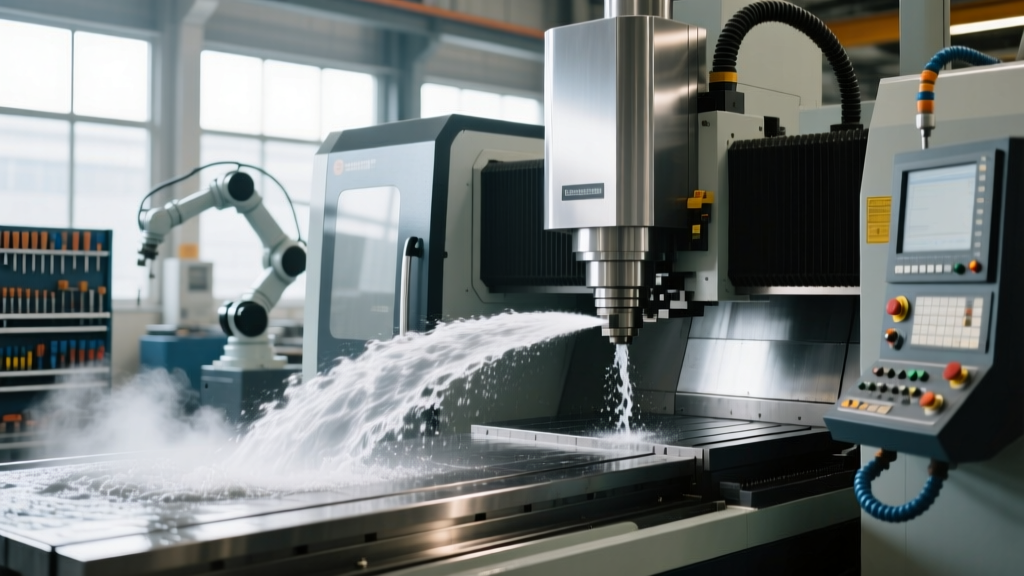
When milling the complex aluminum cam tracks that dictate the braiding rhythm of the hair braiding tool machine, shops frequently use air-over-hydraulic vises like the Kurt DX6 or Kitagawa pneumatic models to speed up loading times. These vises use shop air (typically 90 PSI) to drive a hydraulic intensifier, generating up to 6,000 lbs of clamping force. The critical safety flaw occurs when the shop's central air compressor cycles down, or a localized air leak causes pressure to drop below 60 PSI.
If the pressure drops during a heavy roughing pass, the hydraulic fluid can cavitate, and the vise jaws will retract, launching the cam track across the enclosure. To comply with institutional machine shop safety protocols and general OSHA guidelines, every pneumatic workholding setup must include a pressure-decay safety switch wired directly into the CNC's emergency stop (E-Stop) circuit. If the air pressure falls below 75 PSI, the switch triggers an immediate feed-hold and spindle stop. Additionally, installing a localized pneumatic accumulator tank at the machine base ensures that momentary compressor dips do not trigger false E-Stops or compromise clamping integrity.
Custom Fixture Design and the Fly-Out Hazard
The main chassis of an industrial hair braiding tool machine requires 5-axis milling of deep pockets and angled mounting surfaces. Because standard vises cannot hold these irregular geometries, machinists must design and mill custom tombstone fixtures. The safety compliance of these custom fixtures is often ignored until a catastrophic fly-out event occurs.
Fixture failure typically happens at the mounting interface. Using standard 18-8 stainless steel socket head cap screws to bolt a custom fixture to the machine table is a severe violation of safe machining practices. Stainless steel fasteners are prone to galling and have lower tensile strength than alloy steel. Fixtures must be secured using Grade 8 (or ISO Class 12.9) alloy steel fasteners. For a 1/2-13 bolt, the torque specification must be strictly adhered to (approximately 110 ft-lbs with light oil). Furthermore, the fixture base should incorporate precision ground locating keys that fit into the machine table's T-slots to absorb lateral cutting forces, preventing the bolts from experiencing shear stress.
The 2026 Workholding Compliance Audit Checklist
Shop managers and safety officers should utilize the following actionable checklist to audit workholding setups before initiating production runs for automated textile and cosmetic machinery:
- Verify Interlock Logic: Manually open the chuck guard while the machine is in 'Cycle Start' mode to confirm the spindle immediately drops to zero RPM and the Z-axis retracts.
- Inspect Collet Tapers: Use a go/no-go gauge to check ER and TG collet tapers. Micro-scoring on the taper surface causes uneven clamping pressure, leading to high-RPM vibration and part ejection.
- Test Pressure Decay Switches: Bleed the air line on pneumatic vises using a manual valve and measure the exact time delay before the CNC triggers a feed-hold. It must be under 0.5 seconds.
- Audit Fastener Grades: Physically inspect the head markings on all custom fixture bolts. Replace any unmarked or 18-8 stainless hardware with Grade 8 alloy steel immediately.
- Review RPM Limits in G-Code: Ensure the G50 (Max Spindle Speed Clamp) command is active in the CNC program, preventing operators from accidentally overriding the safe RPM limit established for the specific chuck and workpiece mass.
By treating workholding not just as a tooling expense, but as a critical safety system governed by strict physical and regulatory limits, manufacturers can safely scale the production of complex automation equipment. Utilizing the OSHA Machine Guarding eTool can help shops identify specific blind spots in their lathe and milling center setups, ensuring that the pursuit of micro-precision never compromises operator safety.