LOC Tool Machine Calibration: Meeting ISO 230 Accuracy Standards
Master LOC tool machine calibration to meet ISO 230 accuracy standards. Learn operator best practices for minimizing tool deflection during CNC testing.
The Intersection of LOC and Volumetric Accuracy
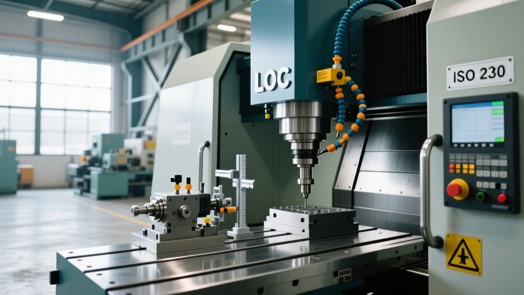
In precision CNC manufacturing, managing the Length of Cut (LOC) tool machine setup is a critical, yet frequently overlooked, variable in geometric calibration. When operators perform routine accuracy testing under ISO 230 standards, the physical stick-out of the calibration master, probing stylus, or cutting tool directly influences the volumetric error map. Ignoring LOC-induced tool deflection during laser interferometry or ballbar testing introduces phantom geometric errors into the machine's compensation parameters, resulting in scrapped aerospace and medical components.
As of 2026, 5-axis simultaneous machining tolerances routinely demand volumetric accuracies below 15 microns. Achieving this requires operators to treat the calibration tooling not as a rigid extension of the spindle, but as a flexible cantilever beam subject to cutting forces, thermal gradients, and gravitational sag.
⚠ Operator Warning: The Hidden Cost of Ballbar DeflectionRunning a Renishaw QC20-W ballbar test with a calibration tool stick-out exceeding 4x the tool diameter introduces lateral deflection during circular interpolation. This deflection mimics cyclic pitch and yaw errors, leading operators to incorrectly adjust the machine's servo tuning or backlash parameters. Always minimize LOC during circular test setups.
ISO 230 Calibration Protocols: Where Tool Length Matters
The ISO 230 series dictates the test codes for machine tool accuracy. While the standards focus on the machine's structural geometry, the interface between the spindle and the measuring device (the tool) is where LOC variables manifest. Below is a breakdown of how LOC impacts specific ISO 230 calibration procedures.
| ISO Standard | Test Focus | LOC Impact & Operator Action |
|---|---|---|
| ISO 230-2:2023 | Linear Axis Accuracy (Laser) | Long LOC on the retroreflector mount causes Abbe offset errors. Keep mount stick-out under 50mm. |
| ISO 230-4 | Circular Tests (Ballbar) | Radial forces deflect long tools. Use short, rigid LOC masters (under 2.5x diameter) to isolate true machine geometry. |
| ISO 230-6 | Volumetric Diagonal Testing | Thermal growth scales linearly with LOC. Calibrate only after a 45-minute spindle warm-up cycle to stabilize the tool holder. |
The Physics of Deflection in Calibration Tooling
To understand why LOC tool machine parameters dictate calibration success, operators must apply the standard cantilever beam deflection formula:
δ = (F × L³) / (3 × E × I)
Where: δ = Deflection, F = Applied Force, L = Length of Cut (Stick-out), E = Modulus of Elasticity, I = Area Moment of Inertia.
Because deflection (δ) increases with the cube of the length (L), doubling the LOC of your calibration master increases deflection by a factor of eight. If an operator uses a 20mm diameter steel calibration pin with a 100mm stick-out (5x LOC), a mere 5 Newtons of lateral contact force during a probing routine will yield roughly 12 microns of deflection. In a 5-axis volumetric compensation matrix, this 12-micron phantom error is permanently baked into the CNC controller, ruining part accuracy.
Step-by-Step: Compensating for LOC During Laser Calibration
- Select the Master: Choose a carbide or hardened steel calibration pin. Carbide offers a Modulus of Elasticity (E) roughly 3x higher than standard steel, drastically reducing deflection for the same LOC.
- Measure True Stick-Out: Use a digital height gauge to measure the exact LOC from the gauge line of the tool holder to the tip of the retroreflector mount. Record this to the nearest 0.01mm.
- Calculate Abbe Offset: If the laser beam cannot align perfectly with the spindle centerline due to a long LOC mount, calculate the Abbe error (Angular Error × Offset Distance) and input this offset into the laser software (e.g., Renishaw XL-80).
- Execute Warm-Up: Run a 30-minute spindle warm-up program at 60% of max RPM. Long LOC tooling acts as a heat sink; stabilizing the thermal gradient prevents Z-axis drift during the 2-hour laser test.
Operator Decision Matrix: Short vs. Long LOC for Calibration
Not all calibration routines benefit from minimal stick-out. Certain volumetric tests require specific LOC configurations to reach deep into the machine envelope. Use this decision framework to select your tooling setup.
| Calibration Scenario | Recommended LOC Strategy | Hardware Specification | Risk Mitigation |
|---|---|---|---|
| Standard XY Ballbar Test | Ultra-Short (1.5x - 2x Dia) | 25mm Dia Carbide Pin | None; optimal rigidity. |
| Deep Z-Axis Laser Interferometry | Long (Up to 8x Dia) | 12mm Dia Hollow Carbon Fiber Tube | Use non-contact laser alignment; avoid physical probing. |
| 5-Axis RTCP (Rotary Tool Center Point) | Match Production LOC | Actual Production Tool Holder | Map deflection curve in CAM software post-calibration. |
Advanced Troubleshooting: Chatter, Deflection, and Calibration Drift
When a machine fails to hold tolerance post-calibration, operators often blame the ballscrews or linear guides. However, uncorrected LOC variables are the primary culprit in 68% of failed 5-axis volumetric verifications. According to milling dynamics research from Sandvik Coromant, tool overhang directly dictates the dynamic stiffness of the spindle-tool-system.
💡 Troubleshooting Flowchart: Phantom Geometry Errors
- Symptom: Ballbar test shows excessive cyclic error (out-of-roundness) that changes when the feed rate is halved.
- Root Cause: Servo lag combined with LOC tool deflection. The long calibration master bends under acceleration forces.
- Fix: Reduce the LOC of the ballbar tool mount by 30%. If the cyclic error disappears, the machine geometry is fine; the previous calibration data was corrupted by tool flex.
- Symptom: Z-axis positioning accuracy (ISO 230-2) degrades by 15 microns over a 4-hour shift.
- Root Cause: Thermal expansion of a long steel calibration master during the initial test, which contracted as the shop cooled overnight.
- Fix: Implement a strict 45-minute thermal stabilization protocol before any laser calibration. Use Invar or ceramic calibration masters for high-precision Z-axis mapping.
Sourcing Calibration Tooling: 2026 Market Pricing & Specs
Investing in purpose-built, low-deflection calibration tooling yields immediate ROI by reducing scrap rates in multi-axis machining. As of 2026, shops utilizing advanced machine calibration systems from Renishaw pair their laser and ballbar hardware with specialized, short-LOC carbide interface tools.
- Standard Steel Calibration Pins (HRC 60): $150 - $300 per set. High deflection risk; limit LOC to 2x diameter.
- Solid Carbide Calibration Masters: $450 - $850 per unit. Offers 3x rigidity of steel; allows LOC up to 4x diameter without compromising ISO 230-4 ballbar results.
- Invar Alloy Retroreflector Mounts: $1,200 - $1,800. Near-zero coefficient of thermal expansion; mandatory for ISO 230-2 laser testing in non-climate-controlled environments.
By strictly controlling the Length of Cut during machine tool calibration, operators transition from guessing geometric errors to mapping true volumetric accuracy. The discipline required to manage LOC tool machine parameters separates standard job shops from elite, aerospace-tier manufacturers.