Troubleshoot Modular Medical Device Manufacturing Equipment
Expert troubleshooting guide for modular medical device manufacturing equipment. Fix shuttle system faults, I/O dropouts, and cleanroom alignment issues.
The Modular Architecture in Medical Manufacturing
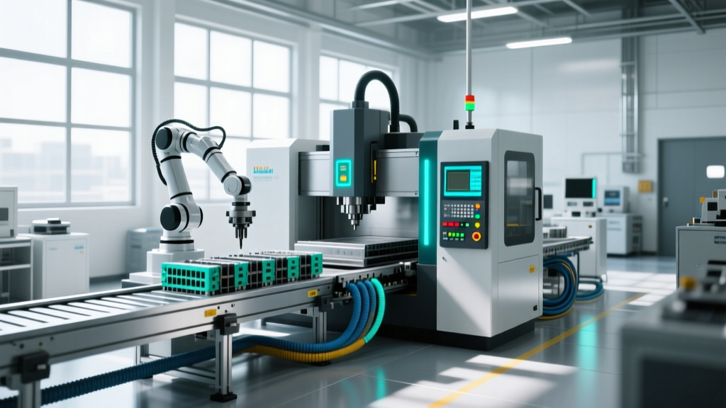
Modern medical device manufacturing equipment has shifted from fixed, hard-automated rotary dials to modular, flexible production systems. This transition is driven by the need to handle high-mix, low-volume production runs for personalized medicine and wearable drug delivery devices. The backbone of these flexible lines includes linear motor shuttle systems (such as the Beckhoff XTS or B&R ACOPOStrak), modular I/O slices, and quick-change kinematic tooling. While these systems offer rapid changeovers, their decentralized nature introduces unique failure modes that traditional maintenance teams often misdiagnose.
Troubleshooting these systems requires adherence to strict quality management frameworks. Under ISO 13485 guidelines for medical device quality management, any equipment repair or parameter adjustment must be documented, validated, and traceable to ensure the final device meets safety specifications. Furthermore, FDA 21 CFR Part 820 mandates that equipment maintenance schedules and calibration records be rigorously maintained, meaning ad-hoc fixes without proper logging can trigger regulatory non-compliance.
Symptom-to-Fix Diagnostic Matrix
Use the following decision matrix to isolate common faults in modular medical assembly cells. This framework prioritizes the most statistically probable root causes based on field service data from ISO Class 7 and 8 cleanroom environments.
| Symptom | Probable Root Cause | Technical Fix & Verification | Est. Cost / Time |
|---|---|---|---|
| Shuttle mover stutters at curve entry | Magnetic rail debris or Hall sensor gap drift | Wipe rail with 99% IPA. Recalibrate mover air gap to exactly 1.5mm using feeler gauges. | $0 / 15 mins |
| EtherCAT bus dropout (Error 0x001A) | EMI from adjacent VFDs or loose RJ45 in I/O slice | Replace RJ45 with shielded M12 connector. Verify 120-ohm termination resistor at bus end. | $45 / 30 mins |
| Kinematic tooling misalignment (>0.05mm) | Wear on tungsten carbide ball/vee interface | Replace Maxwell-style coupling set. Verify pneumatic clamp pressure is minimum 6 bar. | $450 / 45 mins |
| Laser profilometer false rejects | HEPA laminar flow micro-vibrations | Decouple sensor mount from main frame using Sorbothane isolators (durometer 50). | $120 / 1 hour |
Deep Dive: Linear Motor Shuttle System Failures
Linear motor shuttle systems are the primary transport mechanism in flexible medical lines, moving syringes or implantable components between modular stations. The most critical, yet frequently overlooked, failure mode involves the rare-earth magnets embedded in the shuttle movers.
Thermal Demagnetization from Improper Sterilization
In medical manufacturing, components frequently require sterilization. A common operational error is placing shuttle movers in an autoclave. Standard neodymium magnets (NdFeB) used in these movers begin to experience irreversible demagnetization at temperatures exceeding 80°C (176°F). Autoclave cycles typically run at 121°C or 134°C. If a mover is autoclaved, its magnetic flux density drops, causing the servo drive to draw excessive current to maintain position, eventually triggering an overcurrent fault (e.g., Beckhoff Error 0x4310).
Maintenance Directive: Never autoclave shuttle movers. Clean them manually using validated, lint-free wipes soaked in 70% isopropyl alcohol. If a mover exhibits a >15% increase in peak current draw during acceleration, replace the magnet array immediately. Replacement mover costs average $4,200 to $5,500 per unit.Track Contamination in ISO Class 7 Environments
Unlike traditional belt conveyors, modular shuttle tracks feature exposed stator coils and magnetic rails. In tablet compression or powder-filling modules, fine particulate matter can bypass HEPA filtration and settle on the tracks. This debris alters the magnetic reluctance, leading to positioning errors of 0.1mm to 0.3mm—well outside the ±0.02mm tolerance required for micro-fluidic cartridge assembly. Implement a daily automated track-wiping routine using a dedicated, sacrificial 'cleaning mover' equipped with a microfiber pad and electrostatic discharge (ESD) grounding brush.
Modular I/O and Fieldbus Topologies
Flexible medical lines rely on decentralized I/O modules (such as WAGO 750 or Beckhoff EL series) mounted directly on the machine frame to minimize wiring. These slices communicate via high-speed industrial Ethernet protocols like EtherCAT or PROFINET.
Diagnosing Communication Jitter
When a modular assembly cell experiences intermittent, non-repeatable faults—such as a pneumatic valve firing 20 milliseconds late—the culprit is often fieldbus jitter rather than mechanical failure. In 24VDC medical lines, the simultaneous switching of multiple solenoid valves during a tooling changeover can cause voltage sags on the I/O power bus. If the voltage drops below 18VDC for even 2 milliseconds, the I/O slice microcontroller may reset, dropping a single Ethernet frame.
Troubleshooting Steps:
- Connect an oscilloscope to the 24VDC load side of the I/O slice power supply.
- Trigger the machine changeover sequence and capture the voltage waveform.
- If sags below 19VDC are observed, install a 10,000µF capacitor bank across the DC bus terminals of the affected I/O segment, or upgrade to a power supply with a higher peak current rating (e.g., moving from a 10A to a 20A supply).
Quick-Change Tooling and Kinematic Couplings
To achieve flexible production, medical lines utilize quick-change end effectors. These rely on kinematic couplings (often Maxwell or Kelvin mount designs) to ensure that when a tool is swapped, it returns to the exact same spatial coordinate without the need for manual recalibration.
The coupling consists of three hardened tungsten carbide balls mating with three precision-ground V-grooves. Over time, the high-frequency impact of pneumatic clamping (often cycling 10,000 times per shift) causes micro-pitting on the V-groove surfaces. This wear manifests as a rotational error (yaw or pitch) in the end effector.
Verifying Coupling Integrity
Do not rely on visual inspection to diagnose kinematic coupling wear. Instead, perform a repeatability test using a dial indicator or laser tracker:
- Mount a 0.001mm resolution dial indicator to the static machine frame, resting on the tooling plate.
- Command the quick-change mechanism to unclamp and reclamp 50 times.
- Record the Z-axis deviation on each clamp. If the spread (max minus min) exceeds 0.015mm, the kinematic coupling is degraded.
- Replace the coupling set. When installing the new set, apply a molybdenum disulfide (MoS2) dry-film lubricant to the V-grooves to prevent galling and extend service life by up to 300%.
Preventative Maintenance Cadence for Flexible Lines
To maintain FDA compliance and minimize unplanned downtime, modular medical device manufacturing equipment requires a strict, data-driven preventative maintenance (PM) schedule. Ad-hoc maintenance is unacceptable in validated medical environments.
| Interval | Component | Action Required |
|---|---|---|
| Daily | Shuttle Tracks | Run automated cleaning mover. Inspect for particulate buildup. |
| Weekly | Kinematic Couplings | Wipe balls and grooves with IPA. Inspect for micro-pitting. |
| Monthly | I/O Slice Terminals | Torque check all 24VDC and ground screw terminals to 0.5 Nm. |
| Annually | Linear Motor Stators | Megger test stator windings for insulation breakdown (min 100MΩ at 500VDC). |
Mastering the troubleshooting of modular medical device manufacturing equipment requires moving beyond basic mechanical fixes and understanding the intersection of electromagnetics, fieldbus communication, and cleanroom physics. By implementing structured diagnostic matrices and adhering to rigorous PM cadences, facilities can protect both their yield rates and their regulatory standing.