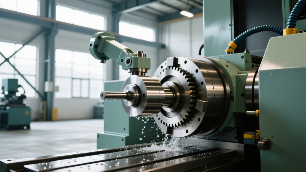
Operator Training for a 5 Axis CNC Machining Center Factory
Master operator training and best practices for your 5 axis CNC machining center factory. Learn RTCP, collision avoidance, and workholding strategies.
The Hidden Economics of 5-Axis Crashes
Transitioning a facility into a modern 5 axis CNC machining center factory requires more than just purchasing a DMG MORI monoBLOCK or a Mazak VARIAXIS. The primary point of failure in multi-axis environments is not machine capability, but operator readiness. A single collision on a 5-axis trunnion table can destroy a $35,000 high-frequency spindle, snap a $4,000 hydraulic workholding system, and result in weeks of downtime while waiting for OEM replacement parts. According to industry data tracked by Modern Machine Shop, shops that implement rigorous, kinematics-specific training programs reduce crash rates by up to 74% in their first year of 5-axis operation.
⚠️ The True Cost of a 5-Axis Collision• Spindle Replacement: $25,000 – $45,000 (plus 3-6 weeks lead time)
• Trunnion Bearing Damage: $15,000 – $22,000
• Machine Geometry Recertification: $4,500 (laser interferometry and ballbar testing)
• Lost Production Revenue: $1,200 – $2,500 per day of downtime
The Paradigm Shift: 3-Axis vs. 5-Axis Operator Mindsets
Operators promoted from 3-axis vertical machining centers (VMCs) often carry over habits that are actively dangerous in a 5-axis environment. In a 3-axis setup, the tool approaches the part strictly from the Z-axis, and clearance is easily visualized. In simultaneous 5-axis machining, the tool vector is constantly changing, and the machine's rotary axes (A/B or B/C) introduce complex kinematic chains where the tool shank, holder, and spindle nose can easily intersect with the table or fixture.
| Operational Concept | 3-Axis VMC Mindset | 5-Axis Machining Center Mindset |
|---|---|---|
| Tool Clearance | Z-axis height dictates safety; X/Y boundaries are static. | Tool shank and holder clearance must be verified against tilting rotary axes and fixture clamps. |
| Work Offsets | G54-G59 set at the top center of the part. | Work offsets must be set at the exact center of rotation (pivot point) of the trunnion or swivel head. |
| Feed Rates | Programmed feed matches tool tip movement directly. | Inverse time feed (G93) or DPM is required; rotary axis acceleration limits must be respected to avoid servo lag. |
| Tool Length | Longer tools are acceptable if Z-clearance is maintained. | Shortest possible tool projection is mandatory to maintain rigidity and avoid kinematic singularities. |
Mastering RTCP and Kinematic G-Code Execution
Rotary Tool Center Point (RTCP) is the foundational technology that makes simultaneous 5-axis machining possible. When RTCP is active, the CNC control dynamically adjusts the linear axes (X, Y, Z) to compensate for the movement of the rotary axes, ensuring the tool tip remains precisely on the programmed surface path. Operators must understand how to invoke and verify RTCP on their specific control architecture.
Control-Specific RTCP Activation
- Fanuc (G43.4 / G43.5): G43.4 is used for tool tip point follow mode. Operators must ensure the tool length offset is active before G43.4 is called, otherwise the control will calculate the pivot point based on the spindle gauge line, resulting in a massive, immediate crash upon rotary movement.
- Heidenhain (PLANE SPATIAL / FUNCTION TCPM): Heidenhain controls use the PLANE SPATIAL cycle to define the working plane tilt. FUNCTION TCPM must be toggled on to maintain the tool tip position during manual jogging or automated repositioning.
- Haas (G128 / G131): On Haas UMC series machines, G128 enables Tool Center Point Control. Operators must use the setting 'TCPC Work Offset' to define whether the offset is measured from the center of rotation or the table surface.
Never run a new 5-axis program with RTCP active at full rapid. Operators should execute the first run with the Z-axis work offset shifted up by +5.000 inches (Z-shift) and the rapid override set to 5%. This allows the operator to visually verify that the tool vector is tilting correctly and that the kinematic chain is behaving as expected without risking the part or fixture.
Workholding Strategies for Multi-Axis Interference Zones
In a 5 axis CNC machining center factory, workholding is not just about clamping force; it is about geometric access. Standard 6-inch Kurt vises are largely obsolete for 5-axis work due to their massive interference footprint. Operators must be trained in low-profile, high-density clamping systems.
Recommended Workholding Systems and Pressures
- Zero-Point Clamping (e.g., Schunk Vero-S, System 3R): These systems allow operators to preload fixtures offline and drop them into the machine with repeatability under 0.005mm. Training must cover the pneumatic/hydraulic release sequences and the strict cleaning protocols required for the clamping pins to prevent chip-induced Z-axis lift.
- Profile Clamping (e.g., Mitee-Bite Pitbull): Essential for 5-sided machining where the vise would block the B or C axis rotation. Operators must be trained to calculate the clamping force relative to the cutting forces. For thin-wall aerospace aluminum (e.g., 7075-T6), clamping pressure should rarely exceed 1,500 PSI to prevent elastic deformation that rebounds once the part is unclamped.
- Thermally Stable Tooling: When running 24/7 lights-out operations, operators must understand the thermal growth of the workholding. Cast iron vises expand differently than aluminum pallets. Best practice dictates using steel or ductile iron base plates and allowing a 45-minute thermal stabilization cycle before probing the final work offset.
Digital Twin Verification and Collision Avoidance
Relying solely on the CAM system's internal machine simulation is a critical vulnerability. CAM post-processors can fail to account for the exact physical dimensions of the machine's sheet metal enclosures, tool changer arms, and specific toolholder flanges. Leading factories mandate the use of independent G-code verification software like CGTech VERICUT or NCSIMUL. These platforms read the actual post-processed G-code and simulate it against a precise digital twin of the specific machine's kinematics.
Operators and programmers must be trained to check for three specific failure modes in the simulation software:
- Near-Miss Collisions: Clearances between the toolholder and the trunnion table that are less than 0.100 inches. Machine servo lag during high-speed contouring can easily close a 0.050-inch gap.
- Axis Limit Violations: Rotary axes hitting their hard limits (e.g., A-axis at +120 degrees) mid-cut, which will trigger an emergency stop and leave tool marks on the part.
- Singularity Errors: Areas where the tool passes directly through the center of rotation of a rotary axis, causing the linear axes to demand infinite velocity to maintain the programmed feed rate.
The 15-Point Daily Startup and Calibration Protocol
A 5-axis machine's volumetric accuracy degrades overnight due to thermal shifts and gravitational sag. Operators must execute a strict daily calibration routine before the first spindle start. According to guidelines supported by workforce development frameworks from the NIST Manufacturing Extension Partnership, standardized daily procedures are the most effective way to reduce scrap rates in high-mix environments.
📋 Daily 5-Axis Startup Checklist- Thermal Warm-Up Cycle: Execute the OEM 20-minute spindle and rotary axis warm-up program to stabilize bearing temperatures.
- Clean Tool Changer Pots: Wipe down the spindle taper and ATC arm grippers with isopropyl alcohol to prevent chip embedding.
- Verify Probe Calibration: Run the spindle probe (e.g., Renishaw OMP60) and tool setter (e.g., Blum TC60) calibration routines. Ensure the standard deviation is below 0.0001 inches.
- Check Kinematic Parameters: On Fanuc controls, verify that the rotary axis center point parameters (e.g., #19700 series) have not been overwritten or drifted.
- Inspect Trunnion Seals: Visually inspect the A and C axis labyrinth seals for coolant ingress or way oil leakage.
- Run a Volumetric Test Part: Cut a standardized 5-axis test piece (like the NAS 979 circle-diamond-square) once a week to track long-term geometric drift.
Building a Culture of Multi-Axis Competency
Operating a 5 axis CNC machining center factory requires shifting from a 'button-pushing' workforce to a team of manufacturing technicians. Operators must be empowered to halt production if a kinematic setup feels incorrect or if a toolholder shows signs of radial runout exceeding 0.0002 inches. Invest in Haimer Safe-Lock toolholders to eliminate tool pullout during heavy 5-axis roughing, and mandate the use of presetter data (RFID chips) to automatically load exact tool lengths and diameters into the control, eliminating manual data entry errors. By combining rigorous simulation, deep kinematic understanding, and strict daily protocols, your facility will unlock the true profitability and precision of 5-axis manufacturing.